6600 Series Push Pull Latch Trim with Mortise Lock – Template
Open the original PDF document
View PDF6600 SERIES INSTALLATION INSTRUCTIONS WITH MORTISE LOCK BODY

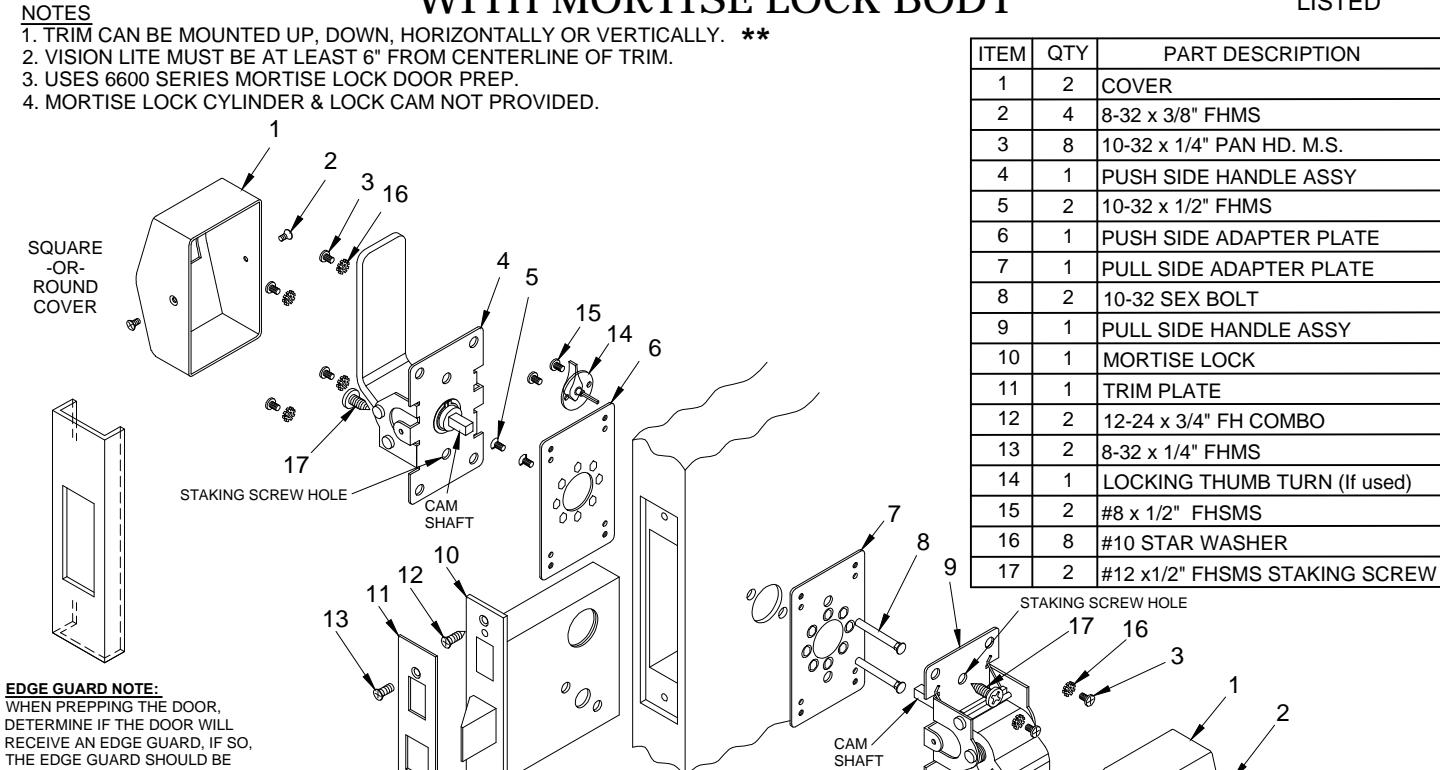
INSTALLED FIRST AND THEN THE PREP FOR THE MORTISE LOCK SHOULD BE MEASURED FROM THE OUTSIDE EDGE OF THE EDGE
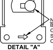
NOTE: BEFORE MOUNTING BASE ASSEMBLIES CAM PIN MUST BE ROTATED TOWARDS SIDE INDICATED BY ARROW STAMPED ON THE BASE.
₩ HANDLES DOWN PUSH PULL PUSH PUSH HANDLES MIXED
HANDLES
INSTALLATION INSTRUCTIONS:
- 1. Install mortise lock (item 10) using (2) 12-24 screws (item 12). Then mount the trim plate (item 11) using (2) 8-32 screws (item 13).
- 2. Install mounting plates: Determine if trim is to be mounted horizontal or vertical. Insert (2) sex bolts (item 8) thru pull side adapter plate (item 7) to match holes on door face. Then place push side adapter plate (item 6) on outside of door and attach with (2) flat head screws (item 5). Do NOT over tighten.
-
3. Assemble trim:
- A) Test both handles to determine which is the push or pull type.
- B) Select the pull trim first. With trim in hand, rotate the cam assembly until the cam pin stops on the appropriate side (see Detail "A").
- C) Place pull side handle on pull side of the door so that cam shaft engages with the mortise lock and fasten with (4) pan head screws (item 3) with (4) star washer (item 17). Test pull side handle (item 9) for latch retraction. If latch does not extend. Loosen both flat head screws (item 5) to adjust alignment.
- D) Mount the push side handle (item 4) using the same method.
- E) Test lock for proper operation.
- F) To prevent the handle assemblies from possible twisting, which in turn can cause binding, determine which staking screw hole will be used for the push and the pull side handle assemblies (the staking screw installs on the staking screw hole location opposite the direction the handle is mounted). Install (1) staking screw on each side using #12 PHSMS (item 17).
- G) Place cover (item 1) over push/pull trims and secure with (2) 8-32 screws (item 2) on each side.
- 4. If provided, install locking thumb turn (item 14) using (2) #8 screws (item 15).
PATENT No. 5,730,478 & 6,196,599

R www.abhmfg.com
E-mail: abhinfo@abhmfg.com Architectural Builders Hardware Mfg., Inc. 1222 Ardmore Ave., Itasca, IL 60143 630.875.9900; FAX 800.9FAXABH (932.9224)
6600-1-10.DWG
PAGE 1 OF 3 REVISED 10-14-19
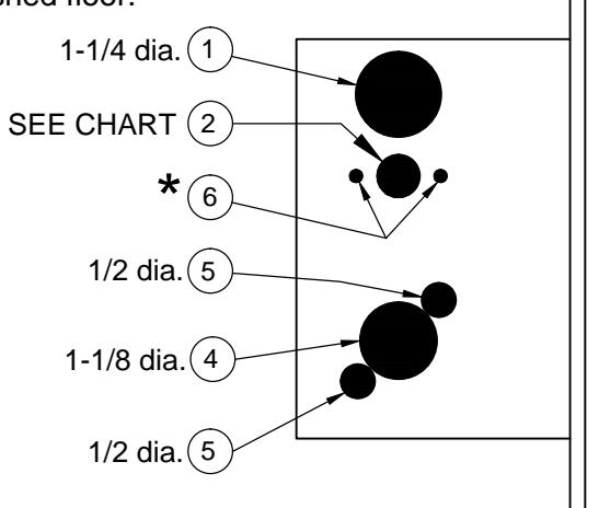
6600 SERIES HOLE PATTERN CHART
Inside holes
| Lockset f | function |
Cylinder
1-1/4" 3: |
Cylinder
1-1/4" dis |
Key | Trim turn knob (9) | ||||
|---|---|---|---|---|---|---|---|---|---|
| 6610 | (Passage/Closet Latchset) | • | |||||||
| 6632 | (Privacy) | ||||||||
| 6637 | (Store Door Lock) | • | • | ||||||
| 6638 | (Entry/Restroom Lock) | • | • | - | |||||
| 6641 | (Asylum Lock) | - | - | - | |||||
| 6645 | (Hotel/Motel Lock) | - | - | ||||||
| 6652 | (Office Lock) | - | - | - | |||||
| 6653 | (Dormitory/Bedroom Lock) | - | - | ||||||
| 6654 | (Entry/Office Lock) | - | - | - | |||||
| 6656 | (Classroom Lock) | • | - | ||||||
| 6657 | (Dormitory Lock) | ||||||||
| 6658 | (Storeroom/Exit Lock) |
★ Determine trim holes based on trim type.
ADA recommends mounting centerline of lock 44" from top of finished floor.
-OR- Check local ordinance for proper height.
Caution: Not all holes shown above need to be drilled. Use the diagram AND the chart to determine the holes that you need to drill for your trim and function combination.
Outside holes

® www.abhmfg.com E-mail: abhinfo@abhmfg.com Architectural Builders Hardware Mfg., Inc. 1222 Ardmore Ave., Itasca, IL 60143 630.875.9900; FAX 800.9FAXABH (932.9224)
6600-2-09.DWG
6600 PAGE 2 OF 3 REVISED 10-14-19
6600 SERIES PUSH/PULL LATCH - DOOR & FRAME PREP
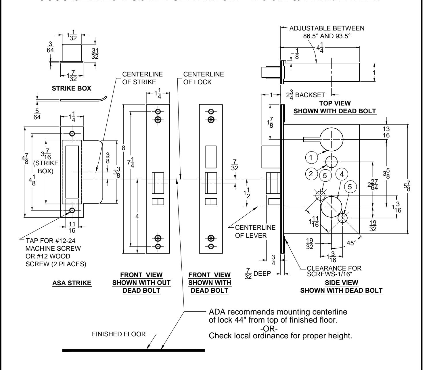
Lock case holes:
- (1) Cylinder hole-1-1/4" dia.
- 2 Turn knob-5/8" dia. / Emergency key-1/2" dia.
- (4) Trim hole-1-1/8" dia.
- (5) Thru-bolt holes- (two required) 1/2" dia.
Notes:
- 1. Before drilling check the hole pattern chart.
- 2. The maximum door-to-frame gap is 3/16".
- 3. Allow 3/64" clearance for the strike box thickness.
- 4. For metal door, lock case support is required from the door manufacturer.
- 5. Tap for a #12-24 machine screw or drill for a #12 wood screw (a combination screw is supplied).

www.abhmfg.com E-mail: abhinfo@abhmfg.com Architectural Builders Hardware Mfg., Inc. 1222 Ardmore Ave. Itasca II, 60143
1222 Ardmore Ave., Itasca, IL 60143 630.875.9900; FAX 800.9FAXABH (932.9224)
hh
PAGE 3 OF 3 REVISED 10-14-19
6600-3-10.DWG
© 2019 ABH Mfg., Inc. printed in USA