6600 C-AB Series Asylum Trim Angle Knob on Both Sides for Mortise Lock
Open the original PDF document
View PDF6600-C-AB SERIES, ASYLUM TRIM ROUND KNOB INSTALLATION FOR MORTISE LOCK
ITEM
1A
2A
OTY
PART DESCRIPTION
"C" ASYLUM TRIM ASSEMBLY
- 1. TRIM MUST BE MOUNTED VERTICALLY.
- 2. VISION LITE MUST BE AT LEAST 6" FROM CENTERLINE OF TRIM.
- 3. USES AB6600 SERIES MORTISE LOCK DOOR PREP.
- 4. MORTISE LOCK CYLINDER & LOCK CAM NOT PROVIDED.
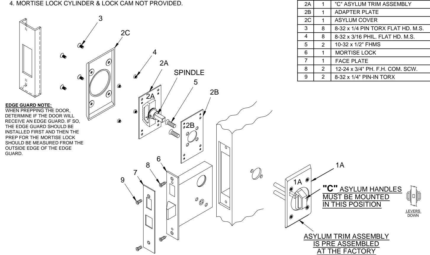
INSTALLATION INSTRUCTIONS:
- 1. Prep for lockbody according to mortise lock manufacturer installation. Install mortise lock (item 6) using (2) 12-24 screws (item 8). Then mount the face plate (item 7) using (2) 8-32 screws (item 9).
-
2. A) Place the pre-assembled asylum trim assembly 1A on the side of the door that will match the diagonal mortise lock mounting through
- B) Place the adapter plate 2B centered with pre-assembled asylum trim assembly 1A while inserting the (2) 10-32 screws (item 5).
- C) After tightening the mounting screws (item 5) test lock and asylum trim assembly 1A for proper latch retraction and knob operation. If the latch does not extend / retract or if trim knob is binding, Loosen 10-32 head screws (item 5) and adjust alignment for proper operation and re-tighten.
- D) Place the asylum trim assembly 2A on the door so that spindle engages with the mortise lock and fasten with (4) 8-32 screws (item 4). Test the knob for latch retraction. If latch does not extend loosen both 10-32 screws (item 5) to readjust alignment and re-tighten.
- E) Place the asylum cover (item 2C) on the asylum trim assembly and screw together with (4) 8-32 screws (item 3).
PATENT No. 6,196,599 & 5,730,478

R www.abhmfg.com E-mail: abhinfo@abhmfg.com Architectural Builders Hardware Mfg., Inc. 1222 Ardmore Ave., Itasca, IL 60143 630.875.9900: FAX 800.9FAXABH (932.9224)
6600-C-AB-1-00 DWG
6600-C-AB PAGE 1 OF 3 ISSUED 02-03-17
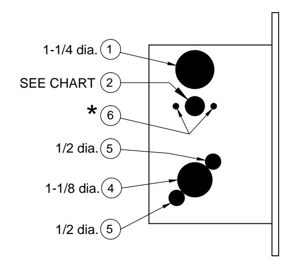
6600-C-AB SERIES, HOLE PATTERN CHART
| Caution: Not all holes shown below need | Inside holes | Outside holes | |||||||||
|---|---|---|---|---|---|---|---|---|---|---|---|
| to be drilled. Use the diagram AND the | 2 | 4 | 5 | 6 | 1 | 2 | 4 | (5) | 6 | ||
| chart to determine the holes that you need to drill for your trim and function | | | | / | 100 | ' // | / | , Kej | 901 | ||||
| combination. | dia dia | ; qou : | . / j |
0
2014 |
ia.(2) | _ // jā | dia. | g. / | dia. | la.(2) | |
| Lockset function |
2.5/jin
1.4/4 |
7um | 5/8" d |
Trim
1-1 |
Thru | * * * * * * * * * * * * * * * * * * * |
1-1/4
1
Emer |
1/2" d |
18/1-1
1-17/1- 1-17/1- |
\`\ | ||
| 6641 (Asylum Lock) | • | - | - | - | • | ||||||
-
★ Determine trim holes based on trim type.
- ADA recommends mounting centerline of lock 44" from top of finished floor.
- -OR- Check local ordinance for proper height.

www.abhmfg.com E-mail: abhinfo@abhmfg.com Architectural Builders Hardware Mfg., Inc. 1222 Ardmore Ave., Itasca, IL 60143 630.875.9900; FAX 800.9FAXABH (932.9224)
6600-C-AB-2-00.DWG
6600-C-AB PAGE 2 OF 3 ISSUED 02-03-17
6600-C-AB SERIES, DOOR & FRAME PREP
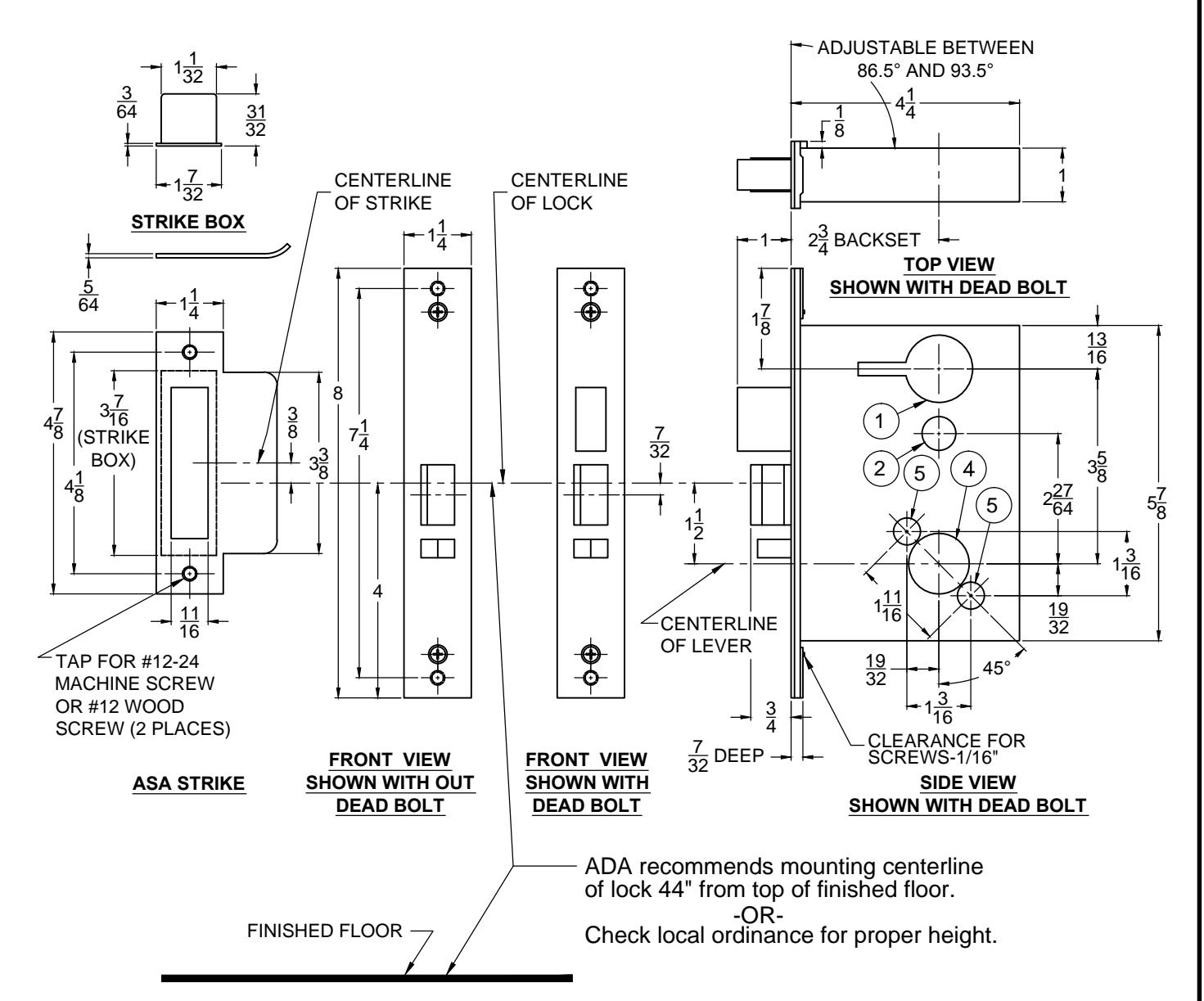
Lock case holes:
- (1) Cylinder hole-1-1/4" dia.
- 2 Turn knob-5/8" dia. / Emergency key-1/2" dia.
- (4) Trim hole-1-1/8" dia.
- (5) Thru-bolt holes-(two required) 1/2" dia.
Notes:
- 1, Before drilling check the hole pattern chart.
- 2, The maximum door-to-frame gap is 3/16".
- 3, Allow 3/64" clearance for the strike box thickness.
- 4, For metal door, lock case support is required from the door manufacturer.
- 5, Tap for a #12-24 machine screw or drill for a #12 wood screw (a combination screw is supplied).

www.abhmfg.com E-mail: abhinfo@abhmfg.com Architectural Builders Hardware Mfg., Inc. 1222 Ardmore Ave., Itasca, IL 60143 630.875.9900; FAX 800.9FAXABH (932.9224)
6600-C-AB-3-00.DW
6600-C-AB PAGE 3 OF 3 ISSUED 02-03-17