6600 B Series Asylum Trim Round Knob for Mortise Lock Template
Open the original PDF document
View PDF6600 "B" SERIES, ASYLUM TRIM ROUND KNOB INSTALLATION FOR MORTISE LOCK
ITEM
QTY
COVER

PART DESCRIPTION
NOTES
- 1. TRIM CAN BE MOUNTED UP. DOWN, HORIZONTALLY, **
- 2. USES A6600 SERIES MORTISE LOCK DOOR PREP.
- 3. MORTISE LOCK CYLINDER & LOCK CAM NOT PROVIDED.
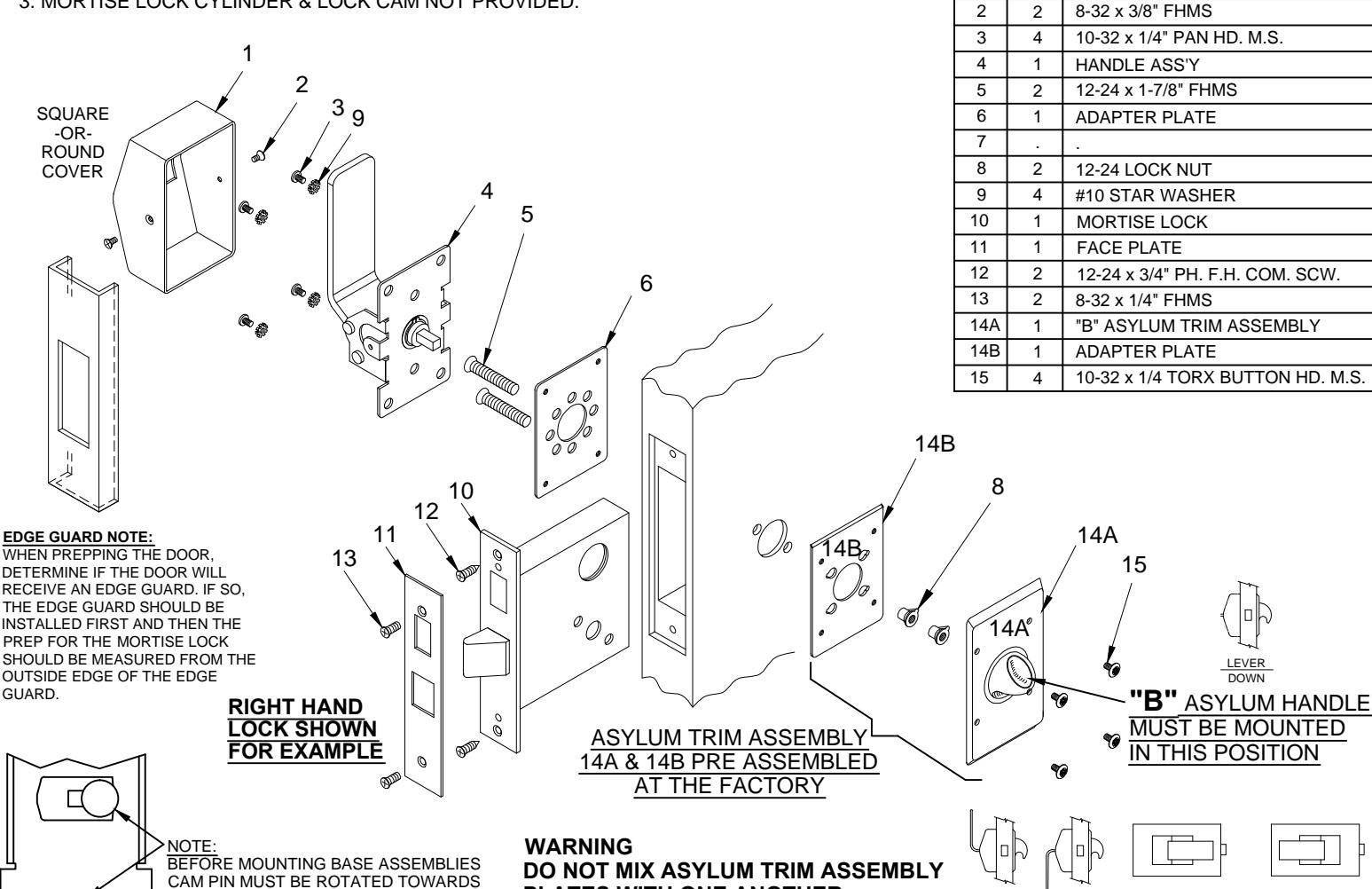
INSTALLATION INSTRUCTIONS:
ON THE BASE.
SIDE INDICATED BY ARROW STAMPED
1. Prep for lock body according to mortise lock manufacturer installation. Install mortise lock (item 10) using (2) 12-24 combination screws (item 12). Then mount the face plate (item 11) using (2) 8-32 screws (item 13).
PLATES WITH ONE ANOTHER
-
2. A) Place the pre-assembled asylum trim assembly 14A & 14B on appropriate side of door.
- B) Then place adapter plate (item 6) on outside of door and attach with (2) 12-24 screws (item 5). Do not over tighten.
-
- A) With trim in hand. Rotate the cam assembly until the cam pin stops on the appropriate side (see Detail "A").
- B) Place handle on the door so that spindle engages with the mortise lock and fasten with (4) 10-32 screws (item 3) with (4) star washer (item 9). Test handle ass'y (item 4) for latch retraction. If latch does not extend. Loosen both 12-24 screws (item 5) to adjust alignment.
- C) Test lock for proper operation.
- F) Place cover (item 1) over the trim and secure with (2) 8-32 screws (item 2) on each side.
PATENT No. 6,196,599 & 5,730,478

R www.abhmfg.com
E-mail: abhinfo@abhmfg.com Architectural Builders Hardware Mfg., Inc. 1222 Ardmore Ave., Itasca, IL 60143 630.875.9900; FAX 800.9FAXABH (932.9224)
(c) 2017 ABH Mfg., Inc. printed in USA
6600-B PAGE 1 OF 3 ISSUED 02-03-17
HANDLE
6600-B SERIES, HOLE PATTERN CHART
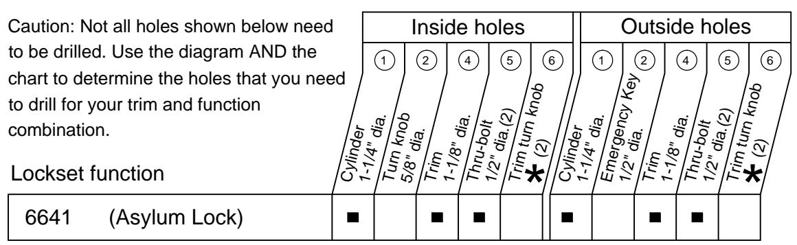
★ Determine trim holes based on trim type.
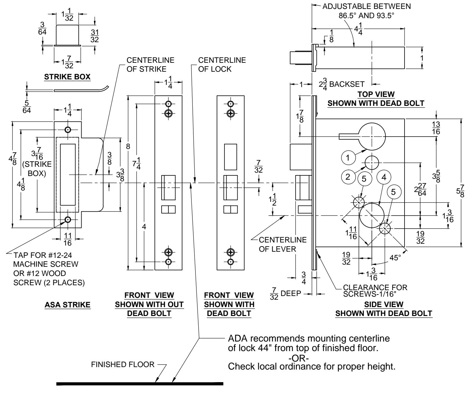
ADA recommends mounting centerline of lock 44" from top of finished floor.
-OR- Check local ordinance for proper height.

® www.abhmfg.com
E-mail: abhinfo@abhmfg.com Architectural Builders Hardware Mfg., Inc. 1222 Ardmore Ave., Itasca, IL 60143
630.875.9900; FAX 800.9FAXABH (932.9224)
© 2017 ABH Mfg., Inc. printed in USA
6600-B PAGE 2 OF 3 ISSUED 02-03-17
6600-B-2-00.DWG
6600-B SERIES, DOOR & FRAME PREP
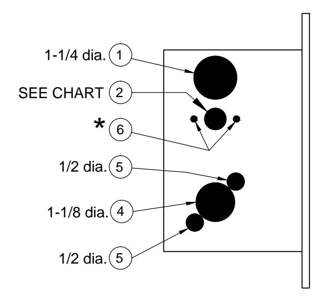
Lock case holes:
- (1) Cylinder hole-1-1/4" dia.
- 2 Turn knob-5/8" dia. / Emergency key-1/2" dia.
- (4) Trim hole-1-1/8" dia.
- (5) Thru-bolt holes-(two required) 1/2" dia.
Notes
- 1, Before drilling check the hole pattern chart.
- 2, The maximum door-to-frame gap is 3/16".
- 3, Allow 3/64" clearance for the strike box thickness.
- 4, For metal door, lock case support is required from the door manufacturer.
- 5, Tap for a #12-24 machine screw or drill for a #12 wood screw (a combination screw is supplied).

@ www.abhmfg.com E-mail: abhinfo@abhmfg.com Architectural Builders Hardware Mfg., Inc. 1222 Ardmore Ave., Itasca, IL 60143 630.875.9900; FAX 800.9FAXABH (932.9224)
© 2017 ABH Mfg., Inc. printed in USA
6600-B PAGE 3 OF 3 ISSUED 02-03-17