6600 B-AB Series Asylum Trim Round Knob on Both Sides for Mortise Lock Template
Open the original PDF document
View PDF6600-B-AB SERIES, ASYLUM TRIM ROUND KNOB INSTALLATION FOR MORTISE LOCK
ITEM
2A
PART DESCRIPTION
"B" ASYLUM TRIM ASSEMBLY
"B" ASYLUM TRIM ASSEMBLY
NOTES
- 1. TRIM MUST BE MOUNTED VERTICALLY.
- 2. VISION LITE MUST BE AT LEAST 6" FROM CENTERLINE OF TRIM.
- 3. USES AB6600 SERIES MORTISE LOCK DOOR PREP.
- 4. MORTISE LOCK CYLINDER & LOCK CAM NOT PROVIDED.
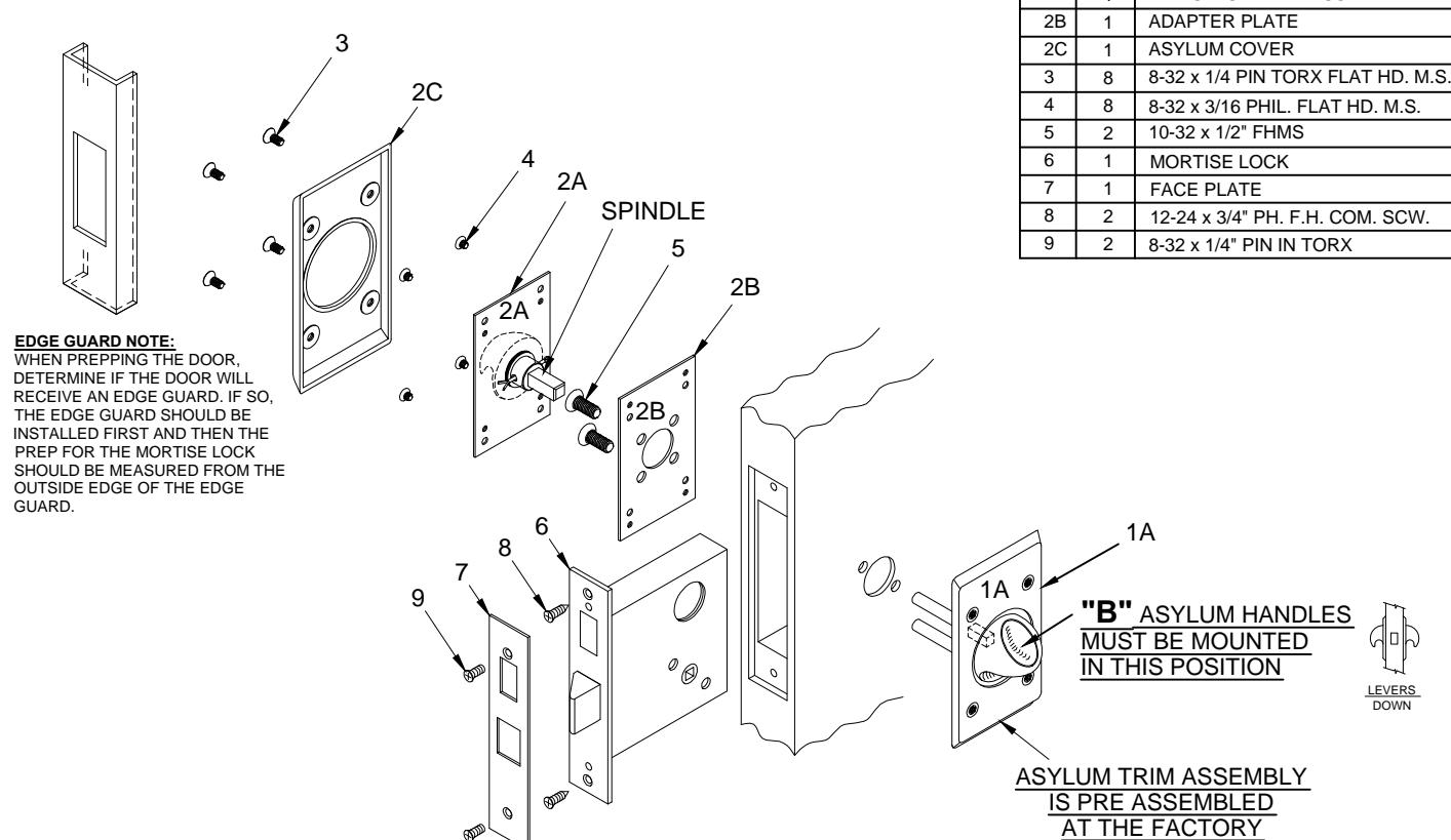
INSTALLATION INSTRUCTIONS:
- 1. Prep for lockbody according to mortise lock manufacturer installation. Install mortise lock (item 6) using (2) 12-24 screws (item 8). Then mount the face plate (item 7) using (2) 8-32 screws (item 9).
-
2. A) Place the pre-assembled asylum trim assembly 1A on the side of the door that will match the diagonal mortise lock mounting through holes.
- B) Place the adapter plate 2B centered with pre-assembled asylum trim assembly 1A while inserting the (2) 10-32 screws (item 5).
- C) After tightening the 10-32 screws (item 5) test lock and asylum trim assembly 1A for proper latch retraction and knob operation. If the latch does not extend / retract or if trim knob is binding, loosen both 10-32 screws (item 5) and adjust alignment for proper operation and re-tighten.
- D) Place the asylum trim assembly 2A on the door so that spindle engages with the mortise lock and fasten with (4) 8-32 screws (item 4). Test the knob for latch retraction. If latch does not extend loosen both 10-32 screws (item 5) to readjust alignment and re-tighten.
- E) Place the asylum cover (item 2C) on the asylum trim assembly and screw together with (4) 8-32 screws (item 3).
PATENT No. 6,196,599 & 5,730,478

R www.abhmfg.com E-mail: abhinfo@abhmfg.com Architectural Builders Hardware Mfg., Inc. 1222 Ardmore Ave., Itasca, IL 60143 630.875.9900; FAX 800.9FAXABH (932.9224)
6600-B-AB PAGE 1 OF 3 ISSUED 02-03-17
6600-B-AB-1-00.DWG
© 2017 ABH Mfg., Inc. printed in USA
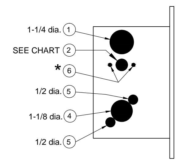
6600-B-AB SERIES, HOLE PATTERN CHART
Caution: Not all holes shown below need Inside holes Outside holes to be drilled. Use the diagram AND the 1 6 1 (2) 6 (2) chart to determine the holes that you need to drill for your trim and function combination. Lockset function 6641 (Asylum Lock)
★ Determine trim holes based on trim type.
ADA recommends mounting centerline of lock 44" from top of finished floor.
-OR- Check local ordinance for proper height.

www.abhmfg.com E-mail: abhinfo@abhmfg.com Architectural Builders Hardware Mfg., Inc. 1222 Ardmore Ave., Itasca, IL 60143 630.875.9900; FAX 800.9FAXABH (932.9224)
6600-B-AB-2-00.DWG
6600-B-AB PAGE 2 OF 3 ISSUED 02-03-17
6600-B-AB SERIES, DOOR & FRAME PREP ADJUSTABLE BETWEEN 86.5° AND 93.5° CENTERLINE CENTERLINE 32 OF STRIKE OF LOCK STRIKE BOX BACKSET TOP VIEW SHOWN WITH DEAD BOLT <u>5</u> 64 13 16 8 <u>3</u> 8 (STŘÍKE BOX) 5 4 CENTERLINE OF LEVER TAP FOR #12-24 45 MACHINE SCREW OR #12 WOOD SCREW (2 PLACES) CLEARANCE FOR DEEP FRONT VIEW SCREWS-1/16" FRONT VIEW ASA STRIKE SHOWN WITH OUT SHOWN WITH SIDE VIEW DEAD BOLT DEAD BOLT SHOWN WITH DEAD BOLT ADA recommends mounting centerline of lock 44" from top of finished floor. -OR-FINISHED FLOOR Check local ordinance for proper height. Notes: 1, Before drilling check the hole Lock case holes: pattern chart. (1) Cylinder hole-1-1/4" dia. 2, The maximum door-to-frame Turn knob-5/8" dia. / Emergency gap is 3/16". 3, Allow 3/64" clearance for the key-1/2" dia. (4) Trim hole-1-1/8" dia. strike box thickness. (5)Thru-bolt holes-4, For metal door, lock case support (two required) 1/2" dia. is required from the door manufacturer. 5, Tap for a #12-24 machine screw or drill for a #12 wood screw (a combination screw is supplied).

@ www.abhmfg.com E-mail: abhinfo@abhmfg.com Architectural Builders Hardware Mfg., Inc. 1222 Ardmore Ave., Itasca, IL 60143 630.875.9900; FAX 800.9FAXABH (932.9224)
6600-B-AB-3-00.DWG
6600-B-AB PAGE 3 OF 3 ISSUED 02-03-17