6200 FM Series Flush Mount Asylum Knob Template
Open the original PDF document
View PDF6200FM SERIES INSTALLATION • FLUSH MOUNT ASYLUM TRIM ON ONE SIDE

PART DESCRIPTION
• 6000 SERIES TRIM ON OPPOSITE SIDE
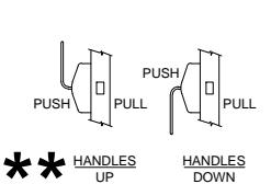
1. TRIM CAN BE MOUNTED VERTICALLY UP OR DOWN. ** 2. VISION LITE MUST BE AT LEAST 6" FROM CENTERLINE OF TRIM
| TE MUST BE AT LEAST 6" FROM CENTERLINE OF TRIM. | 1 | 1 | COVER | |||
|---|---|---|---|---|---|---|
| 1 2 | 2 | 2 | 8-32 x 3/8" FHMS | |||
| 3 | 4 | 10-32 x 1-1/2" PH. TRUSS HD. M.S. | ||||
| 4 | 1 | PUSH OR PULL SIDE HANDLE ASSEMBLY | ||||
| 5 | 2 | #8 x 3/4" PH. FL. HD. W.S. | ||||
| 3 | 6 | 1 | LATCH | |||
| SQUARE | 8 | 7 | 1 | FM TRIM ASSEMBLY | ||
|
-OR-
ROUND COVER |
4 | , | MOUNT |
/ CORRECT VERTICAL BACKSET
TING BEFORE DRILLING. JSE BACKSET TEMPLATE THAT IS SUPPLIED. |
||
ITEM | QTY
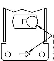
NOTE: BEFORE MOUNTING BASE ASSEMBLIES CAM PIN MUST BE ROTATED TOWARDS SIDE INDICATED BY ARROW STAMPED ON THE BASE.
INSTALLATION INSTRUCTIONS:
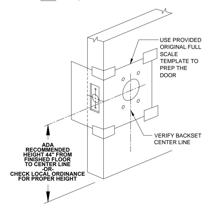
- 1. Prep door according to latch backset, vertical mounting ONLY using backset template.
- 2. Install latch using wood screws (item 5).
- 3. Install pull side trim into door cutout.
- 4. Place push side handle on push side of the door and slide cam shaft into latch cam. Fasten push trim with (4) 10-32 machine screws (item 3).
ALL PREP MOUNTING HOLES-TO BE STRAIGHT & PARALLEL TO ONE ANOTHER, THIS WILL HELP PREVENT ANY BINDING OF MECHANICAL PARTS.
- 5. Test handle for free movement of the latch bolt before tightening all screws. If latch bolt does not extend or retract freely because of any type of binding, Loosen mounting screws to adjust alignment of trim handles and re-tighten screws one at a time while checking latch bolt movement from both handles.
- 6. Test for proper operation and check that the mounting hardware (item 3) & IS TIGHT before proceeding with the next step.
- 7. Place cover (item 1) over 6000 series trim and secure with (2) 8-32 flat head screws (item 2).
PATENT PENDING

@ www.abhmfg.com E-mail: abhinfo@abhmfg.com Architectural Builders Hardware Mfg., Inc. 1222 Ardmore Ave., Itasca, IL 60143 630.875.9900; FAX 800.9FAXABH (932.9224)
6200FM
6200FM PAGE 1 OF 3 ISSUED 05-19-17
6200FM-1-02 DWG
6200FM SERIES PUSH/PULL LATCH - DOOR PREP
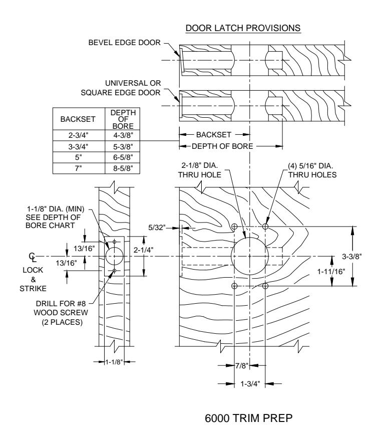
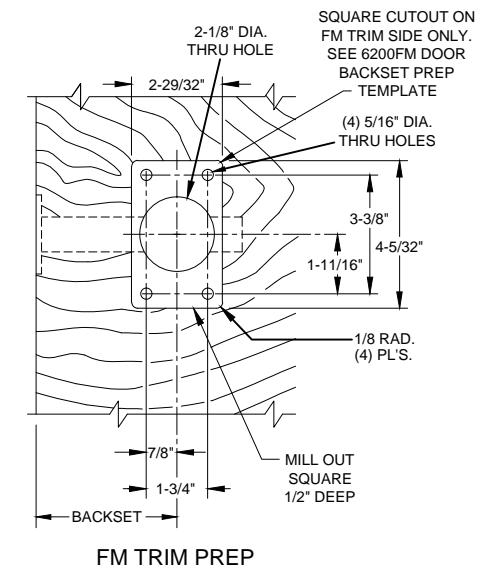
WOOD DOOR
(VERTICAL MOUNTING ONLY SHOWN)
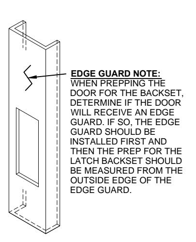
DOOR PREP INFORMATION:
- 1. BACKSET DIMENSION FROM LOW EDGE OF BEVEL.
- 2. CENTER PUNCH ALL HOLES.

@ www.abhmfg.com E-mail: abhinfo@abhmfg.com Architectural Builders Hardware Mfg., Inc. 1222 Ardmore Ave., Itasca, IL 60143 630.875.9900; FAX 800.9FAXABH (932.9224)
© 2017 ABH Mfg., Inc. printed in USA
6200FM PAGE 2 OF 3 REVISED 05-19-17
6200FM-2-02.DWG
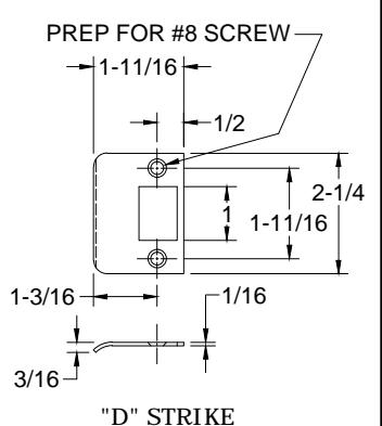
6200FM SERIES PUSH/PULL LATCH - FRAME PREP REINFORCEMENT BY FRAME MFG. G LOCK & STRIKE HALF DOOR THICKNESS DOOR STOP MEASURED FROM STOP OR 1-1/4" SILENCER WHEN USED) +1/64 -0 MORTAR #12-24 TAPPED HOLE GUARD (2 PLACES) 2-1/16" 3-3/8 (MIN) -3/8" 3-3/8" +1/64 LOCK 2-1/16' & STRIKE METAL FRAME (ASA STRIKE SHOWN FOR EXAMPLE)
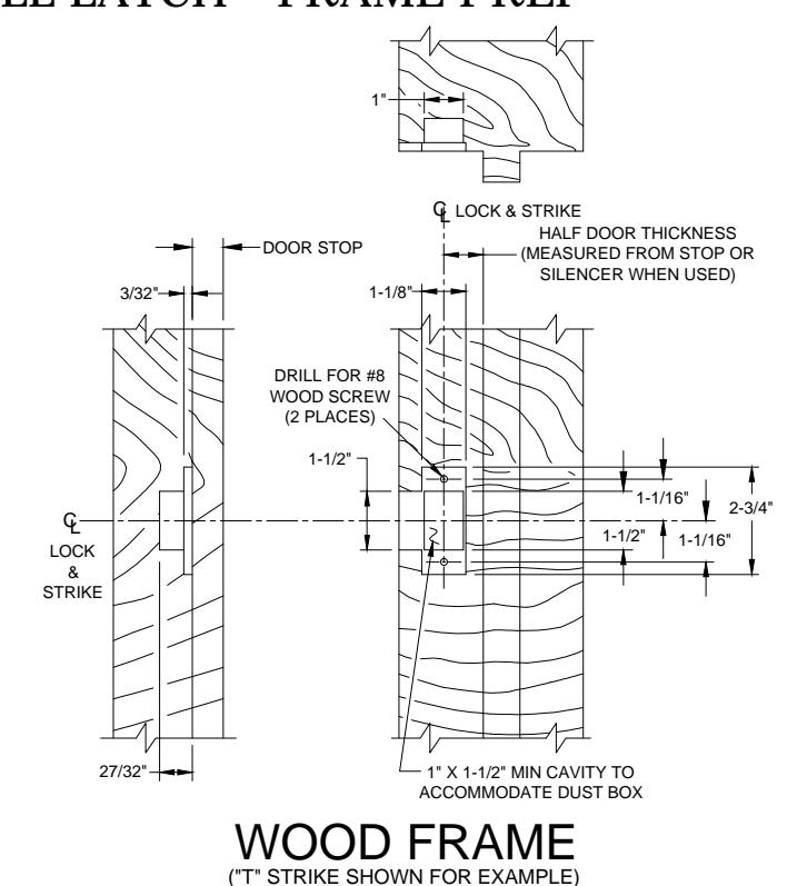
FRAME PREP:
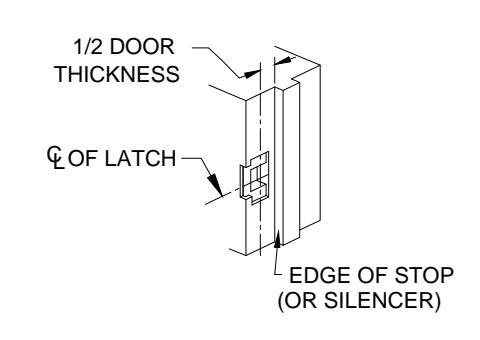
- 1. Mark centerline of latch bolt on frame.
- 2. Center strike and mark screw positions.
- 3. Mortise to required strike and box depth.
- 4. All dimensions in inches.
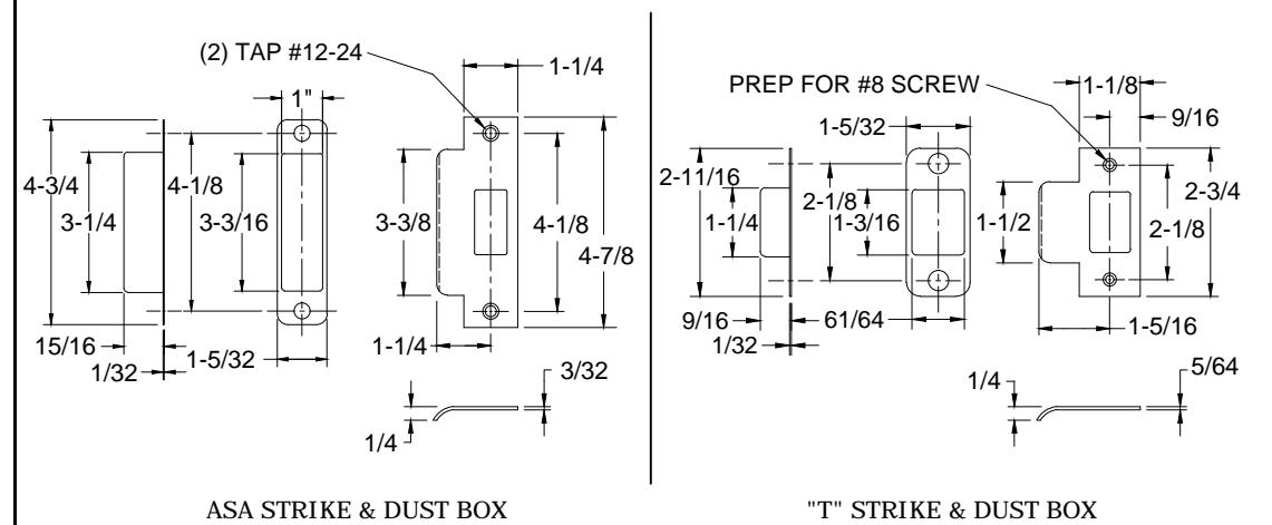
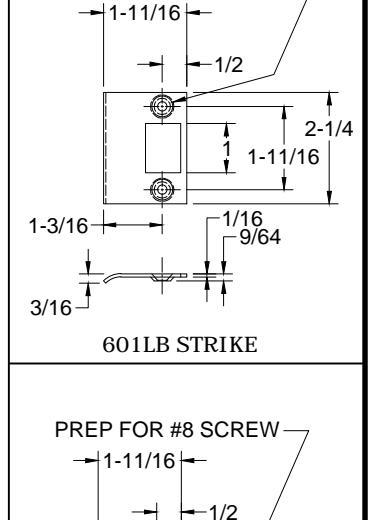
PREP FOR #8 SCREW
6200FM-3-02.DWG

® www.abhmfg.com
E-mail: abhinfo@abhmfg.com Architectural Builders Hardware Mfg., Inc. 1222 Ardmore Ave., Itasca, IL 60143 630.875.9900; FAX 800.9FAXABH (932.9224)
© 2017 ABH Mfg., Inc. printed in USA
6200FM
PAGE 3 OF 3 REVISED 05-19-17