6000 Series Template – Cylindrical Push Pull Latch
Open the original PDF document
View PDF6000 SERIES INSTALLATION
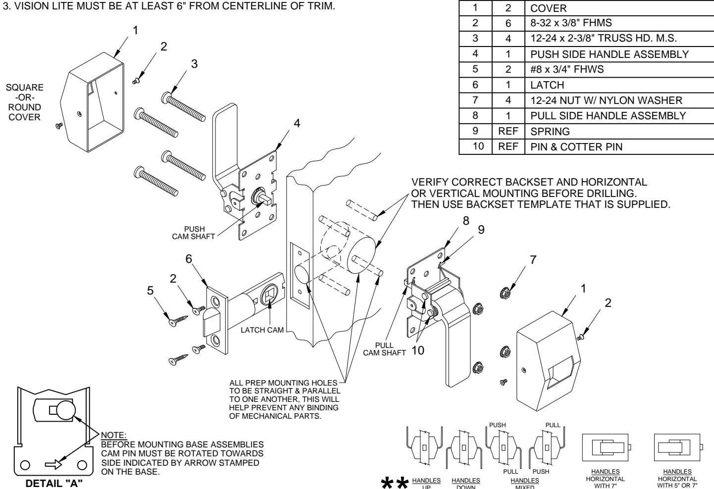
ITEM
QTY

PART DESCRIPTION
NOTES
- 1. TRIM CAN BE MOUNTED UP, DOWN, HORIZONTALLY OR VERTICALLY. **
- 2. USES STANDARD 161 DOOR PREP
- 3. VISION LITE MUST BE AT LEAST 6" FROM CENTERLINE OF TRIM.
INSTALLATION INSTRUCTIONS:
- 1. Prep door according to latch backset and determine if trim is to be mounted horizontal or vertical mounting using backset template.
- 2. Install latch using either wood (item 5) or machine screws (item 2) depending on door type.
-
3. Install trim:
- A) Test both handle assemblies to determine which is the push or pull type.
- B) Select the pull handle assembly (item 8) first.
- C) Place pull handle on pull side of the door and slide cam shaft into latch cam. Then place the push side handle assembly (item 4) on the push side of the door. Slide push side cam shaft into latch cam. By hand, fasten both trim handles with (4) 12-24 machine screws (item 3) and (4) 12-24 hex nuts (item 7). Test both handles for free movement of the latch bolt before tightening all screws. If latch bolt does not extend or retract freely because of any type of binding, loosen mounting screws to adjust alignment of trim handles and re-tighten screws one at a time while checking latch bolt movement from both handles.
- D) Test for proper operation and check that the mounting hardware (item 3) & (item 7) is tight before proceeding with the next step.
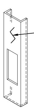
- E) Place covers (item 1) over push and pull trims and secure with (2) 8-32 flat head screws (item 2) on each cover .
PATENT No. 6,196,599

® www.abhmfg.com E-mail: abhinfo@abhmfq.com Architectural Builders Hardware Mfg., Inc. 1222 Ardmore Ave., Itasca, IL 60143 630.875.9900; FAX 800.9FAXABH (932.9224)
6000-1-15.DWG
6000 PAGE 1 OF 3 REVISED 12-28-17
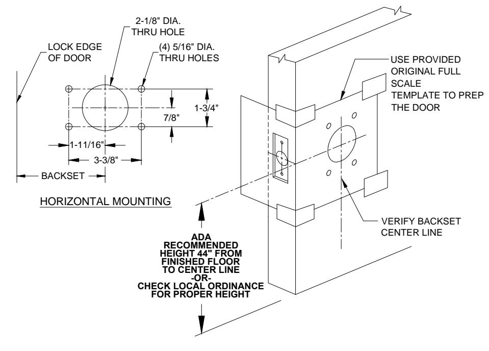
6000 SERIES PUSH/PULL LATCH - DOOR PREP
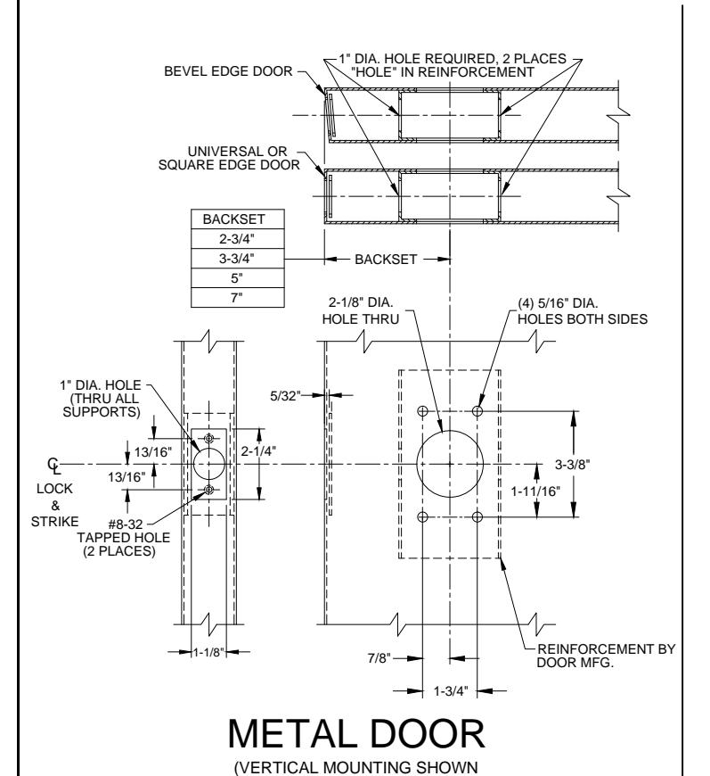
SEE BELOW FOR HORIZONTAL MOUNTING)
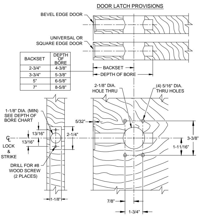
WOOD DOOR
(VERTICAL MOUNTING SHOWN SEE BELOW FOR HORIZONTAL MOUNTING)
DOOR PREP INFORMATION:
- 1. BACKSET DIMENSION FROM LOW EDGE OF BEVEL.
- 2. CENTER PUNCH ALL HOLES.
- 3. DRILL HOLES (FOR HOLLOW METAL DOORS, DO NOT DRILL THRU. CENTER PUNCH & DRILL HOLES FROM BOTH SIDES OF DOOR).
- 4. REINFORCEMENT MUST BE APPLIED ON METAL DOORS AT THE SCREW LOCATIONS.
- 5. REINFORCEMENT TO BE SUPPLIED BY DOOR MANUFACTURER. THE HANDLE ASSYS MUST BE SUPPORTED. THE LATCH BOLT UNIT MUST BE SUPPORTED AND CENTERED WITHIN 1/16" OF THE CENTERLINE AT THE BACK END.
EDGE GUARD NOTE: WHEN PREPPING THE DOOR FOR THE BACKSET, DETERMINE IF THE DOOR WILL RECEIVE AN EDGE GUARD. IF SO, THE EDGE GUARD SHOULD BE INSTALLED FIRST AND THEN THE PREP FOR THE LATCH BACKSET SHOULD BE MEASURED FROM THE OILTSIDE EDGE OF THE

EDGE GUARD.
@ www.abhmfg.com E-mail: abhinfo@abhmfg.com Architectural Builders Hardware Mfg., Inc. 1222 Ardmore Ave., Itasca, IL 60143 630.875.9900; FAX 800.9FAXABH (932.9224)
© 2017 ABH Mfg., Inc. printed in USA
6000 PAGE 2 OF 3 REVISED 12-28-17
6000-2-15.DWG
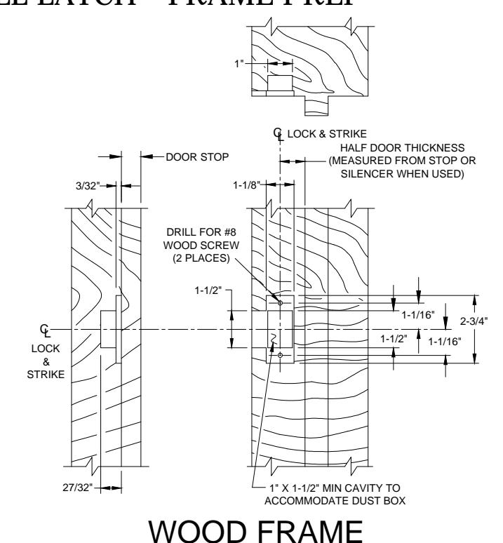
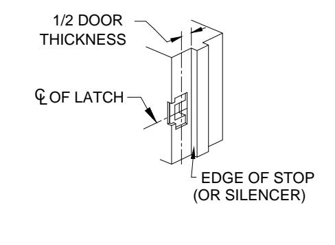
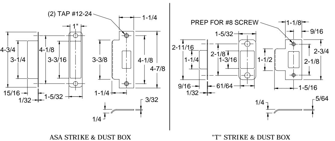
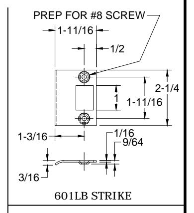
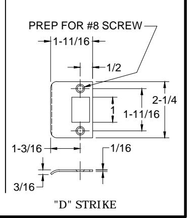
6000 SERIES PUSH/PULL LATCH - FRAME PREP REINFORCEMENT BY FRAME MFG. G LOCK & STRIKE HALF DOOR THICKNESS DOOR STOP MEASURED FROM STOP OR 1-1/4" SILENCER WHEN USED) +1/64 -0 MORTAR #12-24 TAPPED HOLE GUARD (2 PLACES) 2-1/16" 3-3/8 (MIN) -3/8" 3-3/8" +1/64 LOCK 2-1/16' & STRIKE METAL FRAME (ASA STRIKE SHOWN FOR EXAMPLE)
("T" STRIKE SHOWN FOR EXAMPLE)
FRAME PREP:
- 1. Mark centerline of latch bolt on frame.
- 2. Center strike and mark screw positions.
- 3. Mortise to required strike and box depth.
- 4. All dimensions in inches.
6000-3-15.DWG

® www.abhmfg.com
E-mail: abhinfo@abhmfg.com Architectural Builders Hardware Mfg., Inc. 1222 Ardmore Ave., Itasca, IL 60143 630.875.9900; FAX 800.9FAXABH (932.9224)
© 2017 ABH Mfg., Inc. printed in USA
PAGE 3 OF 3 REVISED 12-28-17