6000 Series CM Installation Instructions Rev 10.1 i-cl00451-rev10.1
Open the original PDF document
View PDF

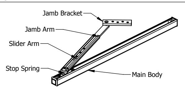
1. PARTS
Screw Chart
| QTY | Screw type | |||
|---|---|---|---|---|
| Jamb | 4 | #9 x 1-1/2" FPHWS | ||
| 4 | 10-32 x 1/2" FPHMS | |||
| Door | 2 | 10-32 x 1-3/8" FPHMS | ||
| 2 | #10 x 1-1/2" PPHWS | |||
| Arm | 3 | 1/4-20 x 1/4" CPSS | ||
| 1 | 1/8" Hex Key | |||
Pre Installation Notes:
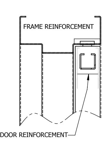
- 1. Hollow metal frames must be properly reinforced with 3/16"(5mm) thick plates that are at least 12"(305mm) long.
- 2. Hollow metal doors must be properly reinforced with 3/16"(5mm) as shown on page 1.
- 3. Hold open(6017) and Friction(6015) are not permitted for use on fire doors.
- 4. Stop only(6016) is subject to job specification for fire door use.
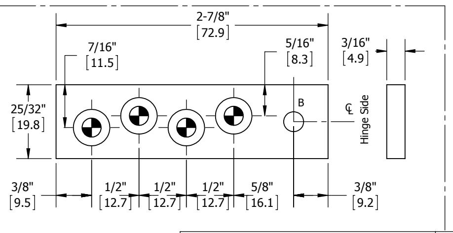
2. INSTALL OVERHEAD DOOR HOLDER/STOP (ODHS) (Right Hand Shown)
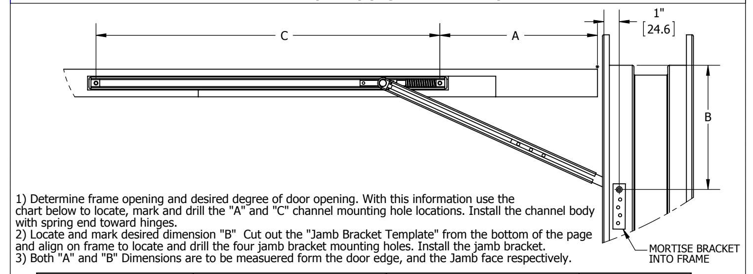
| 85°-95 | ° Opening | 96°-110 | |||||
|---|---|---|---|---|---|---|---|
| Size | Door Width | Α | В | Α | В | С | |
| SZ1 | 18"- 25" | 23/32" [18.2] | 7-1/16" [179.5] | 23/32" [18.2] | 7-1/16" [179.5] | 16-5/16" [414.3] | |
| 25" - 33" | 5" [127] | 5-1/16" [128.7] | 4" [ 101.6] | 5-1/16" [128.7] | 10-5/10 [414.5] | ||
| SZ2 | 33" - 42" | 10" [254] | 8-1/16" [204.8] | 8" [203.2] | 0 1/16" [204 0] | 21-3/4" [552.4] | |
| 42" - 51" | 16" [406.4] | 0-1/10 [204.0] | 14" [355.6] | 0-1/10 [204.0] | 21-3/4 [332.4] | ||
All dimensions shown in [] are in millimeters
DRAWING NO: I-CL00451 REV: 10 SHEET 1 OF 3
HAGER COMPANIES 139 Victor Street, St. Louis, MO 63104 - (800) 325-9995 - Fax (800) 782-0149

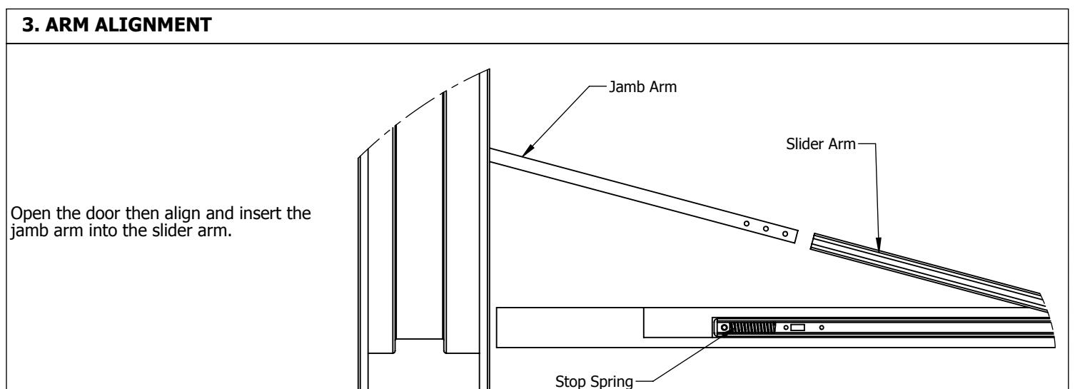
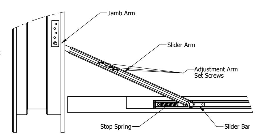
4. SETTING DESIRED DOOR OPENING
If it applies, disengage the hold open engagement switch (step 5a). With the door held at the desired maximum opening angle, position the slider bar against the stop spring. Tighten the three adjustment arm set screws. Tighten to a minimum of 20 in-lbs (WARNING: over tightening may result in damage to the main arm).
If dead stop is required, position the door 5-7 degrees less then the desired dead stop. Then tighten as instructed above.
switch OFF position
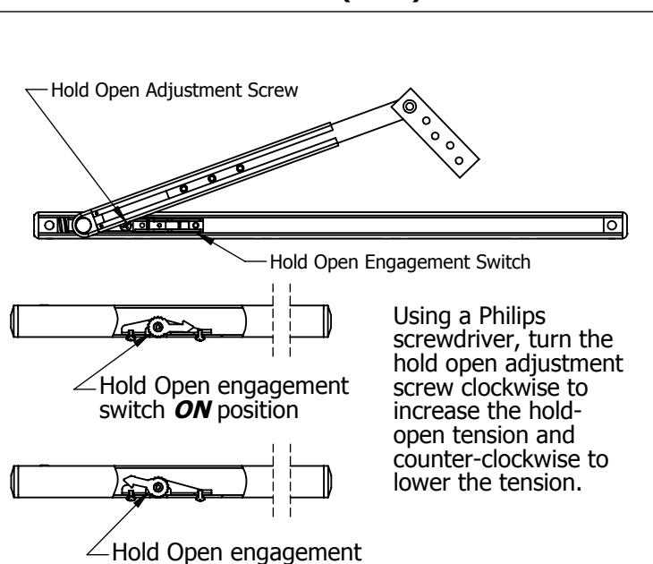
5a. OPTIONAL HOLD OPEN (6017) 5b. OPTIONAL FRICTION HOLD OPEN (6015)
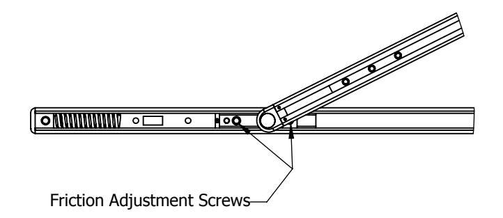
Using a Hex Key, turn the friction adjustment screws clockwise to increase the friction and counter-clockwise to lower the friction. Pressure should be evenly distributed across both screws
DRAWING NO: I-CL00451 REV: 10 SHEET 2 OF 3
HAGER COMPANIES 139 Victor Street, St. Louis, MO 63104 - (800) 325-9995 - Fax (800) 782-0149

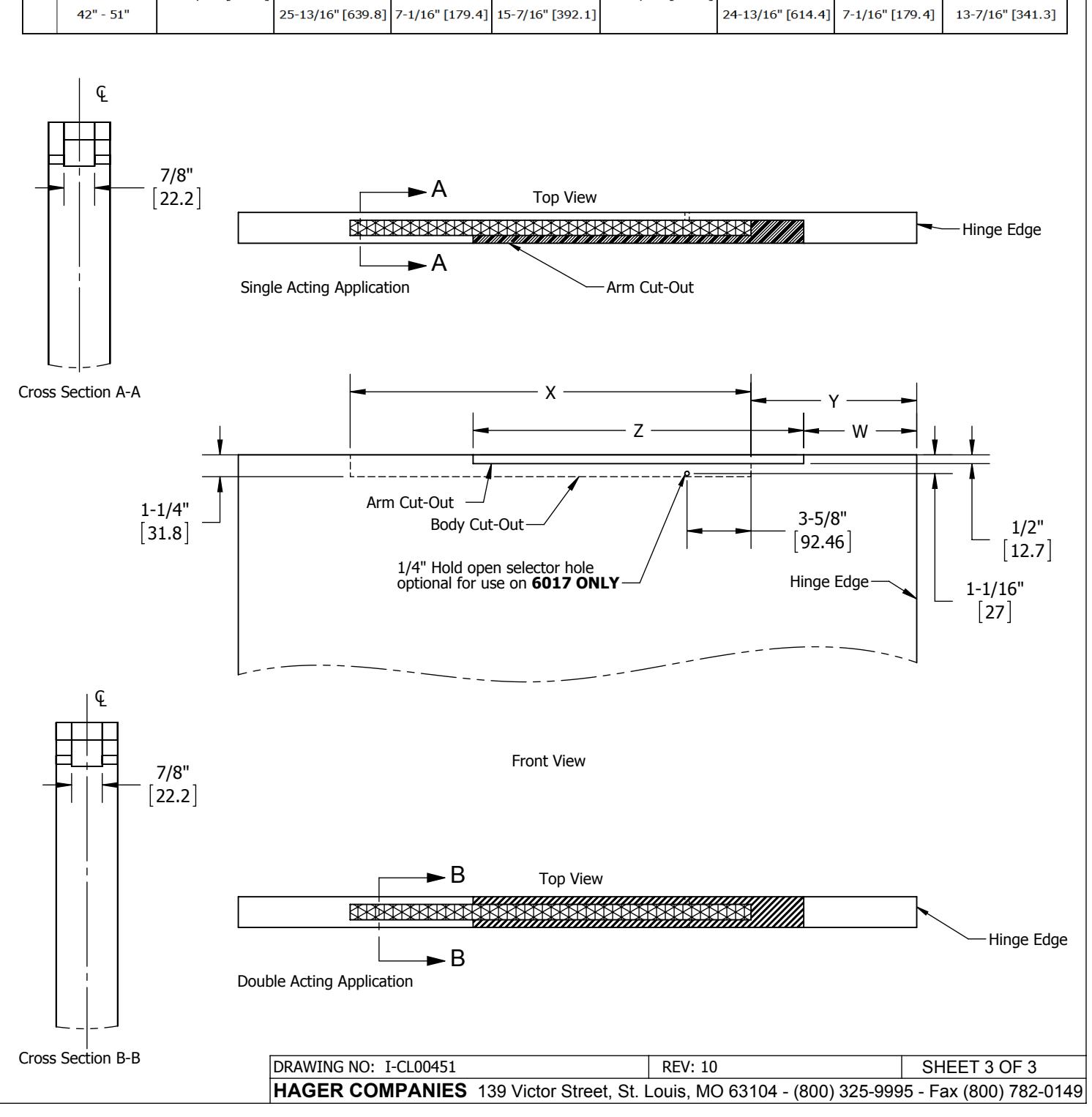
DOOR PREP FOR ALL STYLES OF HOLD OPENS AND STOPS
| Size | Frame Opening | 85°-95° Opening | 96° - 110° Opening | ||||||
|---|---|---|---|---|---|---|---|---|---|
| x | Z | w | Υ | x | Z | w | Υ | ||
| 1 | 18" - 25" | - 17-3/8" [441.3] | 12" [ 304.8] | SAME AS 'Y' | 1/4" [6.4] | 17-3/8" [441.3] | 12" [ 304.8] | SAME AS 'Y' | 1/4" [6.4] |
| 25" - 33" | 13-3/8" [339.7] | 3-7/16" [87.3] | 4-7/16" [112.7] | 13-3/8" [339.7] | SAME AS 'Y' | 3-7/16" [87.3] | |||
| 2 | 33" - 42" | - 22-13/16" [579.4] | 18-13/16" [477.8] | 6-7/16" [163.5] | 9 7/16" [239.7] | 22-13/16" [579.4] | 18-13/16" [477.8] | 6-15/16" [176.2] | 7-7/16" [188.9] |
| 42" - 51" | 25-13/16" [639.8] | 7-1/16" [179.4] | 15-7/16" [392.1] | 24-13/16" [614.4] | 7-1/16" [179.4] | 13-7/16" [341.3] | |||