57- Delayed Egress for 80 Series Exit Devices to ElectroLynx Connector System Installation
Open the original PDF document
View PDFInstallation Instructions

Delayed Egress 57-80 Series
Exit Device

This product can expose you to lead which is known to the state of California to cause cancer and birth defects or other reproductive harm. For more information go to www. P65warnings.ca.gov.
1-800-727-5477 • www.sargentlock.com
Attention Installer: Improper installation may result in damage to the product and void the factory warranty.
Exit Device
Installation Instructions

| TOC | Table of Contents | ||||
|---|---|---|---|---|---|
| 1 | Warning | ||||
| 2 | General Description | 4 | |||
| 3 | Component Installation | 5 | |||
| 4 | Cylinder Installation | 8 | |||
| 5 | Factory Default Settings | 9 | |||
| 6 |
DIP Switch Settings
10 |
||||
| 7 | Wiring11 | ||||
| 8 | Exit Device Plug-in Connector Installation14 | ||||
| 9 | Sample Wiring Instructions15 | ||||
| a | Basic 57- Delayed Egress with Fire Alarm and Remote Reset15 | ||||
| b | 57- Exit Device with inside Keypad, Fire Alarm, Door Status and Remote Horn16 | ||||
| c | 57- Exit Device with Fire Alarm, Keypads and Fail Safe ET17 | ||||
| 10 | Operating Instructions18 | ||||
| a |
Power Up Sequence
15 |
||||
|
b
Modes of Operation16 |
|||||
| 11 |
Troubleshooting
21 |
||||
| a | Diagnostic and Insert LEDs21 | ||||
| b |
Rim, Mortise and Vertical Rod Exit Devices
22 |
||||
| c | Minimum Requirements for Arming Rail (Delayed Egress Mode)22 | ||||
| d | Symptom/Failure23 | ||||
Exit Device
Installation Instructions

1 Warning
FCC :
This equipment has been tested and found to comply with the limits for a Class B digital device, pursuant to Part 15 of the FCC Rules. These limits are designed to provide reasonable protection against harmful interference in a residential installation. This equipment generates, uses, and can radiate radio frequency energy and, if not installed and used in accordance with the instructions, may cause harmful interference to radio communications. However, there is no guarantee that interference will not occur in a particular installation. If this equipment does cause harmful interference to radio or television reception, which can be determined by turning the equipment off and on, the user is encouraged to try to correct the interference by one or more of the following measures:
- Reorient or relocate the receiving antenna.
- Increase the separation between the equipment and receiver.
- Connect the equipment into an outlet on a circuit different from that to which the receiver is connected.
- Consult the dealer or an experienced radio/TV technician for help.
Industry Canada :
This Class B digital apparatus meets all requirements of the Canadian Interference Causing Equipment Regulations. Operation is subject to the following two conditions: (1) this device may not cause harmful interference, and (2) this device must accept any interference received, including interference that may cause undesired operation.
Cet appareillage numérique de la classe B répond à toutes les exigences de l'interférence canadienne causant des règlements d'équipement. L'opération est sujette aux deux conditions suivantes: (1) ce dispositif peut ne pas causer l'interférence nocive, et (2) ce dispositif doit accepter n'importe quelle interférence reçue, y compris l'interférence qui peut causer l'opération peu désirée.
"This equipment complies with FCC radiation exposure limits set forth for an uncontrolled environment. This equipment should be installed and operated with minimum distance 20cm between the radiator and your body. This transmitter must not be co-located or operating in conjunction with any other antenna or transmitter."
Under Industry Canada regulations, this radio transmitter may only operate using an antenna of a type and maximum (or lesser) gain approved for the transmitter by Industry Canada. To reduce potential radio interference to other users, the antenna type and its gain should be so chosen that the equivalent isotropically radiated power (e.i.r.p.) is not more than that necessary for successful communication.
Conformément à la réglementation d'Industrie Canada, le présent émetteur radio peut fonctionner avec une antenne d'un type et d'un gain maximal (ou inférieur) approuvé pour l'émetteur par Industrie Canada. Dans le but de réduire les risques de brouillage radioélectrique à l'intention des autres utilisateurs, il faut choisir le type d'antenne et son gain de sorte que la puissance isotrope rayonnée équivalente (p.i.r.e.) ne dépasse pas l'intensité nécessaire à l'établissement d'une communication satisfaisante.

Any retrofi t or other fi eld modifi cation to a fi re rated opening can potentially impact the fi re rating of the opening, and SARGENT Manufacturing makes no representations or warranties concerning what such impact may be in any specifi c situation. When retrofi tting any portion of an existing fi re rated opening, or specifying and installing a new fi re-rated opening, please consult with a code specialist or local code offi cial (Authority Having Jurisdiction) to ensure compliance with all applicable codes and ratings.
Exit Device
Installation Instructions

2
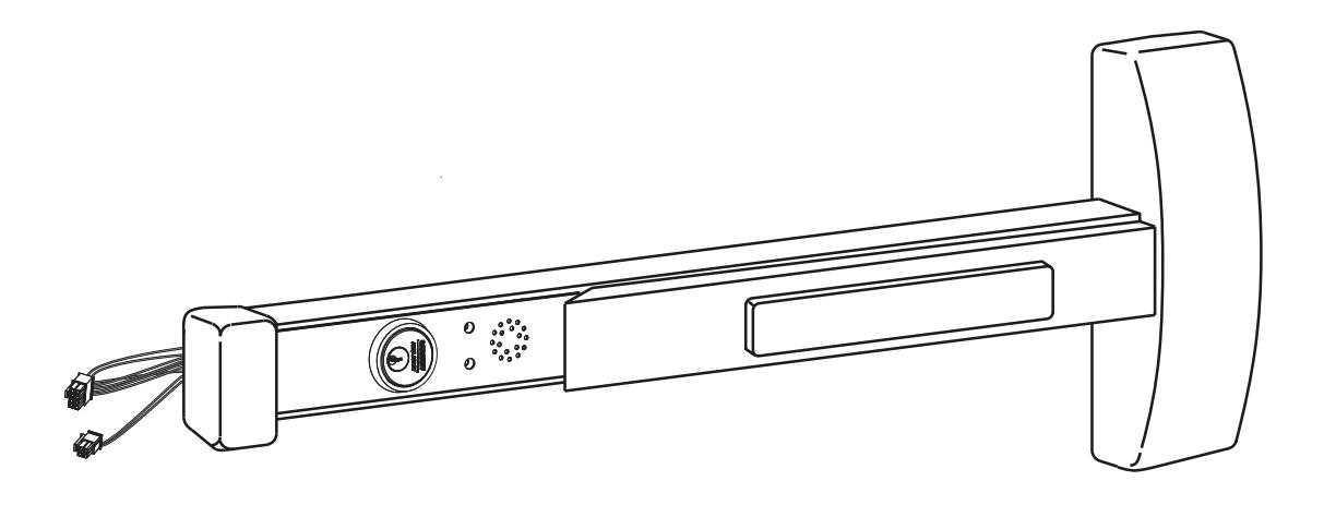
General Description
The SARGENT 57-Delayed Egress Exit Device is designed to work with an external electromagnetic lock in areas that require a delayed egress which alarms at the door when any attempt is made to violate the door. The 57- device can be tied into a fire alarm system.
Note:
Proper connections and appropriate peripheral hardware are required.
BC-Prefix Option
The BC prefix for 57- indicates that the unit has been programmed to comply with the section of the BOCA code relating to delayed egress.
BOCA allows for automatic reset of the delayed egress unit. Under BOCA, the unit can automatically reset thirty (30) seconds after the door has been cycled. If the door is opened any time during the thirty (30) seconds, the timer in the unit resets and waits another thirty (30) seconds before rearming. This requires a door position switch.
Note:
If a door position switch is not used (Blue wire connected to Black wire), the unit will automatically reset in 30 seconds.
Electrical Specifications
- Input Voltage: 24VDC +/- 15% (20.4 27.6VDC) regulated/filtered
-
Power Consumption @ 24VDC (with 1584 Electromagnet):
- 60 mA (typical) Disarmed;
- 220 mA (typical, unloaded) Armed;
- 250 mA (typical) Delayed Egress Mode;
- 375 mA (max, loaded) with Optional Features
- Operating Temp: 0°C to 49°C (32°F to 120°F)
- Maximum Electromagnetic Lock load: 275mA. If desired load exceeds this limit, an external relay module may be used.
All components must be installed according to prevailing electrical codes.
There are no user serviceable parts on the 57- PCB module assembly.
2
Parts Breakdown
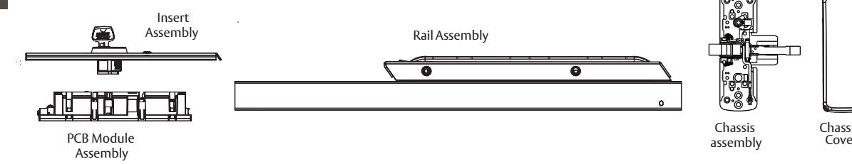
| Part Number | Description |
|---|---|
| 52-4830 | PCB Module Replacement Pack - Standard |
| 52-4831 | PCB Module Replacement Pack - BOCA (BC prefix) |
| Consult factory | Rail Assembly |
| Consult factory | Chassis Assembly |
| Consult factory | Insert Assembly |
| Consult factory | Chassis Cover |
A7743F 1/23
and more open world

Installation Instructions

3 Component Installation
- 1. Determine locations of components at the door.
- 2. Mount all hardware and peripheral equipment according to manufacturer's instructions.
Note:
For exit device mechanical installation, refer to mechanical instruction sheets and templates included with product.
- Power supply should be mounted near door to avoid power drop due to excessive wire runs.
- Features used will determine wire requirements of electric hinge or other power transfer.

Installation Instructions

3 Component Installation (Continued)
Verify hand and bevel of door. Exit devices are always reverse bevel and are mounted on the inside of the door.
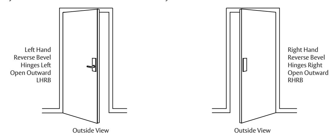
On inside of door, exit devices are oriented as follows:
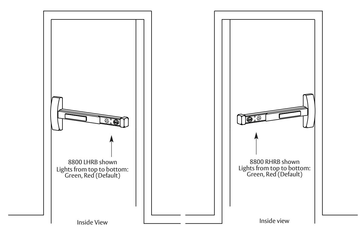
All subsequent illustrations in this document are shown as RHRB.
and/or patent www.assaabloydss.com/patents.

Installation Instructions

3 Component Installation (Continued)
ElectroLynx® Connector System Notes
The system is designed to be installation friendly with pluggable connectors from the electric hinge through the door to the rail. The only wiring required is to the fl ying leads on the pigtail harness assembly on the frame side of the electric hinge.
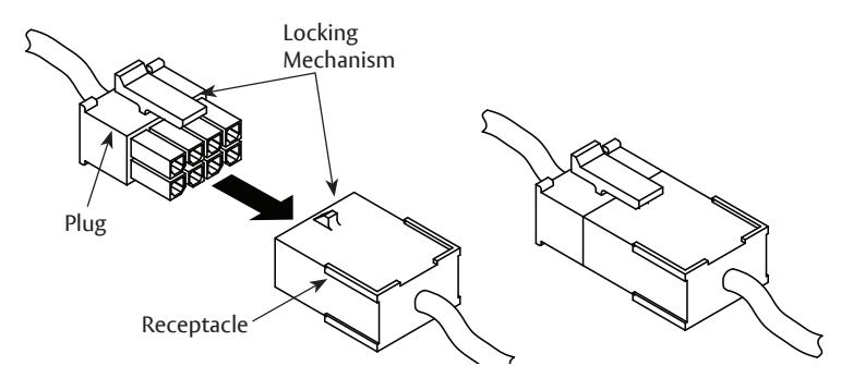
Important:
The plug and receptacle connectors are designed to mate and lock together as shown in the fi gure. Plug the connectors onto each other with the locking mechanism aligned as indicated.
Do NOT force connectors on any other way
57- Exit Device - ElectroLynx Wiring Notes (Consult factory for assistance if required)
- The ElectroLynx connector system is designed to be installation friendly with pluggable connectors from the electric hinge through the door to the rail. The rail, raceway, electric hinge, and pigtail harness connector terminations and wire colors all match.
- For most applications, an 8-pin electric hinge is required.
- Plug raceway connectors into ElectroLynx hinge connectors. Hard wire to corresponding pigtail harness wires as required.
Installation Notes :
- With new applications, a raceway harness with 8- and 4-pin connectors will be pre-installed inside the door by ASSA ABLOY door manufacturer when specifi ed during the ordering process. Raceway harness kits are also available for retrofi t applications. (For retrofi t applications, refer to retrofi t instructions.)
- If door does not have a raceway harness with connectors, either consult factory for raceway retrofi t kit or cut connectors off product and hard wire, as required.
- Wiring to pigtail harness is per facility wiring requirement. The rail, raceway, electric hinge and pigtail connector ( - +) terminations and wire colors all match.
Exit Device
Installation Instructions

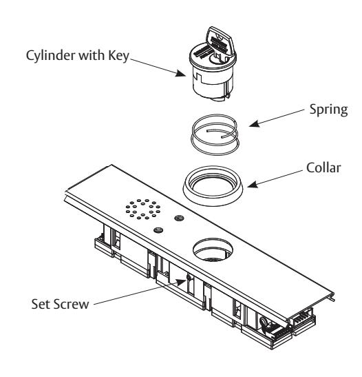
4 Cylinder Installation
- 1. Prepare door according to template(s) and instructions supplied with exit device.
- 2. Verify cylinder (size varies; consult factory) is installed in rail insert with collar prior to installing exit device on door.
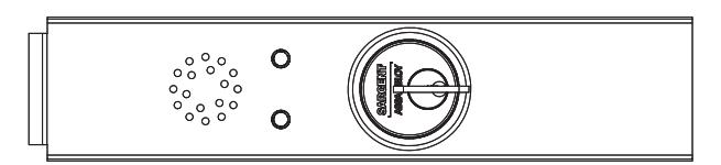
Top View of Insert
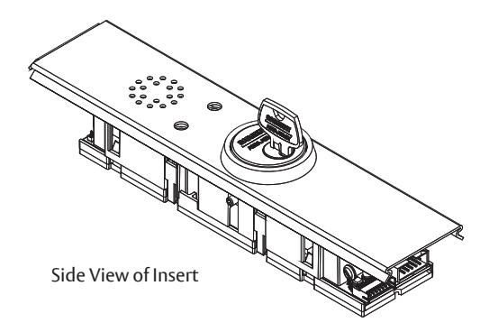
Remove and Replace Cylinder
- 1. Ensure power is disconnected.
- 2. Loosen set screw by turning counter-clockwise using 5/64" allen wrench.
- 3. Extract and slide cylinder through spring and collar.
Note:
When replacing cylinder, slide cylinder through spring then collar, taking care to orient cylinder as shown. Hold cylinder into proper position and slowly tighten set screw until cylinder is securely held by set screw. Do NOT overtighten set screw.
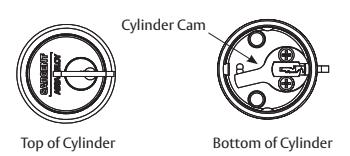
Cylinder Orientation
See illustration on circuit board for correct orientation of cylinder when installing.
Note:
The proper position of cam allows for removal of key.
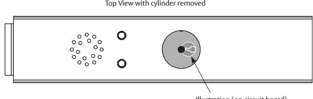
Illustration (on circuit board)
Exit Device
Installation Instructions

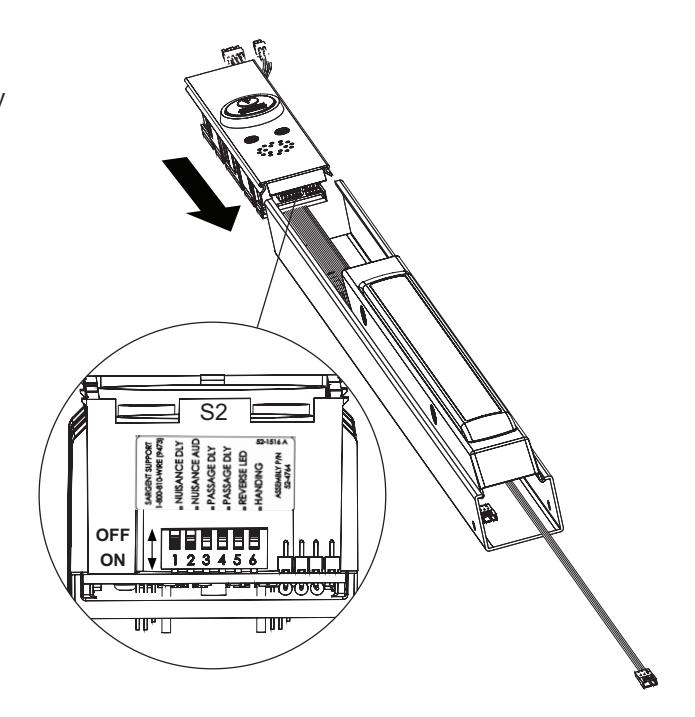
5 Factory Default Settings
After verifying the factory default settings for the DIP switch, install the insert assembly to the rail assembly.
If default feature settings need to be changed, carefully slide the insert assembly from the rail assembly to make the proper DIP switch adjustments.
For example, solid RED can be set to indicate that the rail is "Armed" with solid GREEN indicating that rail is "Disarmed".
Note:
Use caution when removing insert assembly to avoid damaging the rail harness connected to the PCB module assembly.
Default factory presets for the 57- are as follows:
| Status | LEDs/Time | Horn |
|---|---|---|
| Armed (Delayed Egress) | Solid GREEN | Off |
| Momentary Egress (Passage Delay) | Flashing RED for 5 seconds | Off |
| Disarmed | Solid RED | Off |
| Alarm | Flashing RED and GREEN 15 seconds for egress | On |
| Nuisance Delay | 1 second | On |
| Nuisance Audible | On | |
| Momentary Egress Time | 5 seconds | |
| Reverse LED | RED (Armed) | |
| Handing | "Top" LED (Armed) for LHRB or RHRB |
Exit Device
Installation Instructions

6 DIP Switch Settings
S2-1 Nuisance Delay (Field selectable 0 or 1 second)
A one second nuisance delay can be enabled by setting Dip Switch (S2-1) to the "On" position. When nuisance delay is enabled, the unit will require the push bar to be depressed for more than one second in order to trigger an irreversible alarm condition. If the push bar is released before the 1 second has elapsed, the unit will go back into the "delayed egress mode" and the alarm will not sound. Nuisance delay is set to "On" position at factory.
If the Dip Switch S2-1 is in the "Off" position, there will be no nuisance delay and alarm horn will sound immediately when the push bar is depressed.
S2-2 Nuisance Audible (Field selectable on or off)
An audible horn is enabled by setting Dip Switch S2-2 to the "On" position. The internal horn will sound as soon as the push bar is depressed, signaling that the device is armed. If the pushbar is held down for more than 1 second, an irreversible alarm condition begins. If Dip Switch S2-2 is in the "Off" position, the horn will not sound during nuisance delay.
Nuisance audible is set to "On" position at factory to sound horn when rail is depressed during nuisance delay.
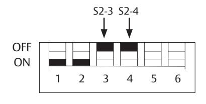
S2-3 & S2-4 Momentary Egress Time
Used to select the momentary egress time of 5, 10, 20 or 40 seconds. This switch is preset at the factory for fi ve seconds.
| S2 DIP Switch position | ||
|---|---|---|
|
S2-3
S2-4 |
Momentary Egress Time | |
| OFF | OFF | 5 seconds (default) |
| OFF | ON | 10 seconds |
| ON | OFF | 20 seconds |
| ON | ON | 40 seconds |
S2-5 Reverse LED (Field selectable green or red)
When S2-5 is "Off" the exit device LED is green when in armed mode (default) and red when in maintained or momentary egress mode. When S2-5 is "On" the exit device LED is red when in armed mode and green when in maintained or momentary egress.
S2-6 Handing (Field selectable LHRB or RHRB)
For a LHRB exit device S2-6 is "Off" for the top LED on the insert to be used when the device is armed. For a RHRB exit device S2-6 is "On" for the top LED on the insert to be used when the device is armed.

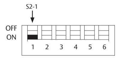
ON - 1 second Nuisance Delay OFF - No Nuisance Delay
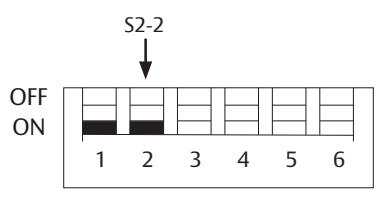
ON - Nuisance Audible On OFF - Nuisance Audible Off
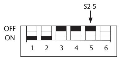
ON - Red (Armed); Green (maintained or momentary egress)
OFF - Green (Armed); Red (maintained or momentary egress)
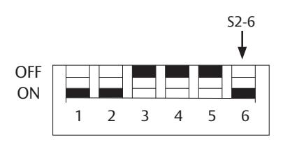
ON - RHRB; Top LED indicates "Armed" OFF - LHRB; Top LED indicates "Armed"
Exit Device
Installation Instructions


7 Wiring

Caution :
Disconnect all input power before beginning installation to prevent electrical shock and equipment damage.
Important:
- Installer must be a trained, experienced service person
- All wiring must comply with applicable local electrical codes, ordinances and regulations
- Field cut rail assemblies are not allowed. Exit device must be ordered for specifi c door width.
Installation Notes:
- 1. With new applications, a raceway harness with 8 & 4-pin connectors will be pre-installed inside the door by ASSA ABLOY door manufacturer when specifi ed during the ordering process. Raceway harness kits are also available for retrofi t applications. (For retrofi t applications, refer to retrofi t instructions)
- 2. If door does not have a raceway harness with connectors, either consult factory for raceway retrofi t kit or cut connectors off product and hard wire, as required.
- 3. Wiring to pigtail harness is per facility wiring requirement. The rail, raceway, electric hinge and pigtail connector ( - +) terminations and wire colors all match.
- 4. **55- only (option) Switch contact rating: 2A @ 30VDC.
- 5. Tape or cap off ends of unused pigtail wires (not shown) to ensure that they do not short.
A7743F 1/23

Installation Instructions

7 Wiring (Continued)
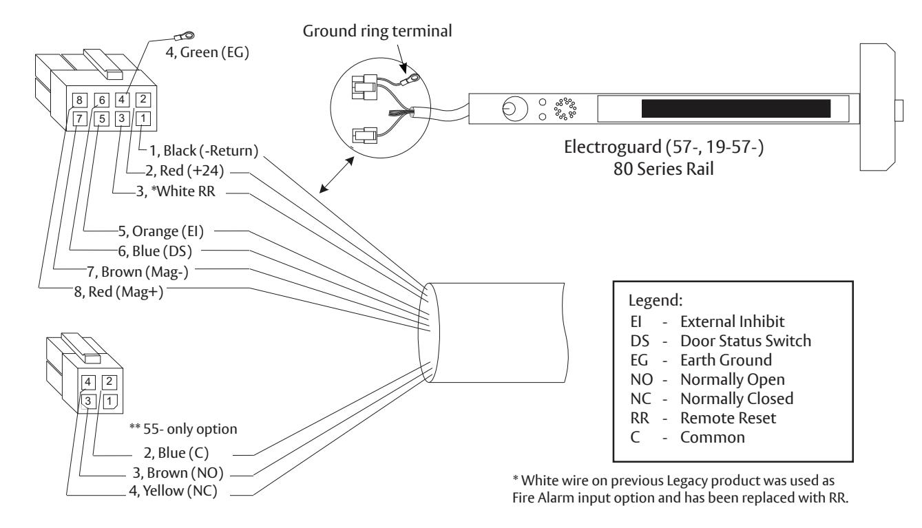
The following are the input and output connector designations.
|
Harness Connector
PIN No.* |
Circuit Board
PIN No. |
Input/
Output |
Harness
Wire Color |
Function |
|---|---|---|---|---|
| 8-2 | J1-1 | input | Red | +24VDC power |
| 8-1 | J1-2 | input | Black |
-Return
N.O. N.C. |
| 8-3 | J1-4 | input | White |
N.O.
Remote reset |
| 8-5 | J1-5 | input | Orange |
External inhibit - disarm unit from
i/s or o/s (key switch, card reader, keypad) |
| 8-6 | J1-6 | input | Blue | Door position sensor (Door Status/Monitor) |
| 8-4 | Chassis | Ground | Green | ESD (Earth) Ground |
| 8-7 | J1-8 | output | Brown | -Return Magnet - |
| 8-8 | J1-10 | output | Red | +24VDC Magnet |
* Example: 8-2 is the 8-pin connector position #2.
Exit Device
Installation Instructions

7 Wiring (Continued)
|
Harness Connector
PIN No.* |
I/O Circuit
Board PIN No. |
Function |
|---|---|---|
| 8-2 | J1-1 |
24VDC Power Supply Input (+)
This input may be tied to the normally closed contact of a building's fi re alarm system. If the fi re alarm is activated, this contact will open, voiding the 15 second delay for egress. |
| 8-1 | J1-2 | Return - Power Supply -return (-). |
| 8-3 | J1-4 |
Remote Reset - This input may be tied to a momentary normally open contact at a
remote location to reset the device when in alarm. Additionally when the device is armed this input may be used for momentary egress with the time per the DIP switch settings. Note: Previous Fire Alarm Input option has been replaced with Remote Reset. |
| 8-4 |
Chassis
Ground |
Chassis Ground - The chassis ground wire must terminate at earth ground of the
equipment power supply or the main power source. |
| 8-5 | J1-5 |
External Inhibit Input - Used to provide remote override of the delayed egress when
in the armed condition. Most common external inhibits are: card readers, keypad, key switches, or remote control console. More than one external inhibit device must be wired in parallel. |
| 8-6 | J1-6 |
Door Position Sensor - An external door status switch can be connected to the 57- to
provide additional security. If the door status switch is utilized, an irreversible alarm will sound if the door is forced open while the device is armed. Unit will not arm if door is not shut. Once the irreversible alarm sounds, it will have to be reset at the door. If the door status switch is not utilized, connect the Blue wire to Return (Black wire) of the 5-pin harness. |
| 8-7 | J1-8 | Return Magnet - |
| 8-8 | J1-10 |
+24VDC Output Magnet
External Magnet Connection - This output can supply up to 275mA load to an external magnet. This output may be connected to a 24VDC relay module if load shall exceed 275mA. |
and/or patent www.assaabloydss.com/patents.

Installation Instructions

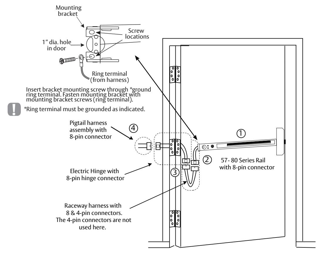
8
Exit Device Plug-in Connector Installation
Note:
No field rail cutoff allowed. Exit device must be ordered for specific door width.
-
1. Mount exit device per instruction sheet provided.
- To insure trouble free operation, check that the push rail can be fully depressed. On vertical rod exit devices, check that the latch bolts do not go into hold back position until the push rail is fully depressed.
- 2. Plug rail connector into raceway connector then feed through 1" hole in door. Install rail mounting bracket with two screws supplied. Install rail end cap.
- 3. Plug raceway connector into electric hinge connector then feed through door prep. Mount electric hinge to door.
-
4. Go to
A
if wiring now. Go to
B
if wiring is to be done later.
- A. Refer to sections 8 and 9. Wire loose frame side wires to loose wires on pigtail harness as required using connectors allowed by local code. Plug pigtail harness connector into electric hinge connector. Feed harnesses through frame prep and mount electric hinge. Refer to operating instructions in section 10. Apply power and test exit device.
- B. Plug pigtail harness connector into electric hinge connector. Feed harnesses through frame prep and mount electric hinge.
A7743F 1/23
and more open world
Exit Device
Installation Instructions

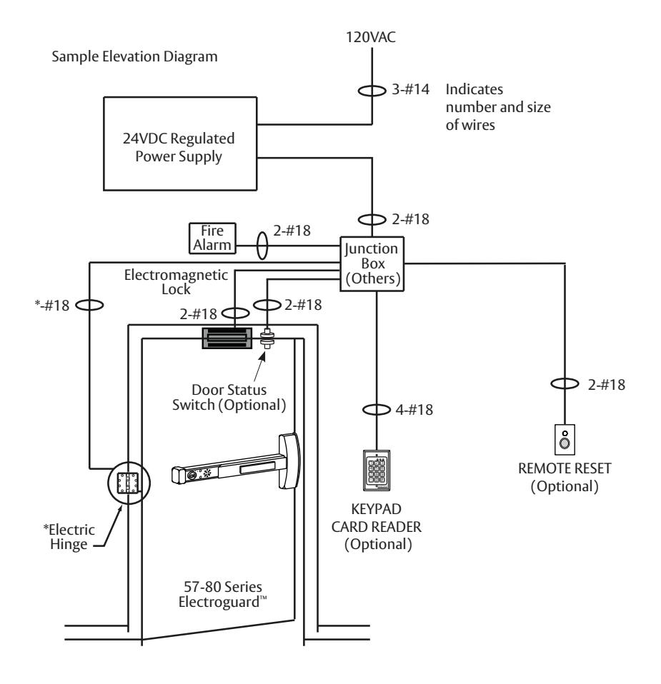
9 Sample Wiring Instructions
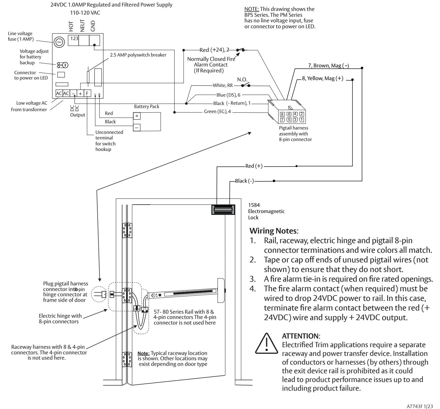
a Basic 57- Delayed Egress with Fire Alarm and Remote Reset
During a fi re alarm condition, the fi re alarm contact opens which de-energizes the rail magnet and allows immediate egress.
Exit Device
Installation Instructions


Wiring Notes:
Sample Wiring Instructions

57- Exit Device with inside Keypad, Fire Alarm, Door Status and Remote Horn
A valid code entry at the 4291 (Inside) keypad shunts the 57- exit device and allows egress for a time period programmable at the keypad. During a fire alarm condition, the contact opens which de-energizes the external electromagnet and allows immediate egress. When the rail is armed and the door is forced open, the 3287 door status switch signals the rail sounding the rail alarm.

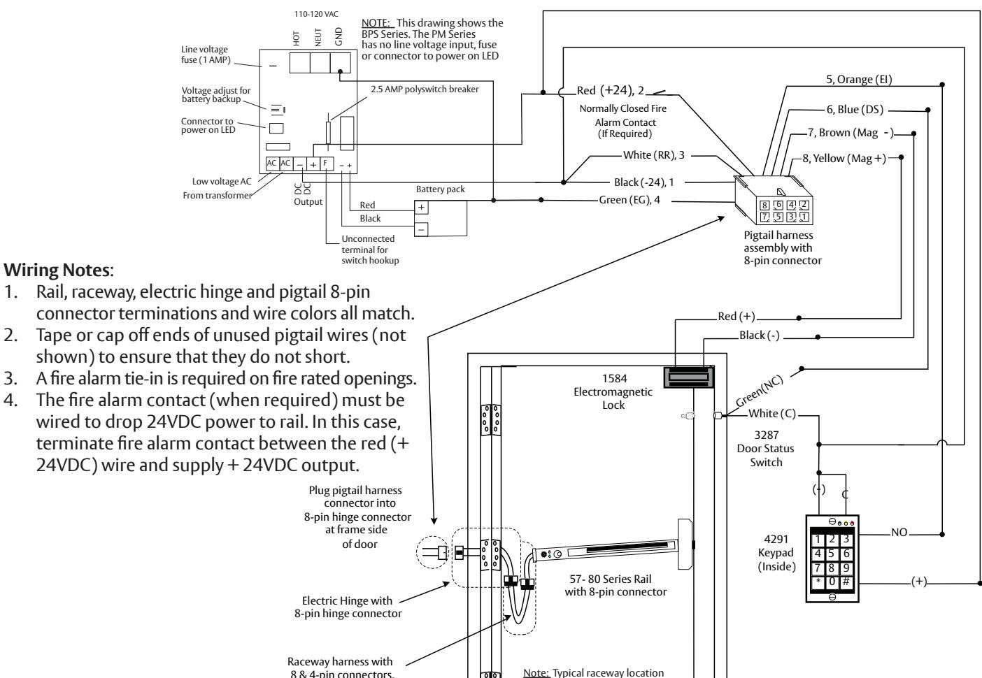

ATTENTION:
Electrified Trim applications require a separate raceway and power transfer device. Installation of conductors or harnesses (by others) through the exit device rail is prohibited as it could lead to product performance issues up to and including product failure.
The 4-pin connectors are not used here.
A7743F 1/23
is shown. Other locations may exist depending on door type
Exit Device
Installation Instructions


Wiring Notes :
colors all match.
do not short.
rated openings.
9 Sample Wiring Instructions

c 57- Exit Device with Fire Alarm, Keypads and Fail Safe ET
During a fi re alarm condition, the contact opens which de-energizes the rail electromagnet and allows immediate egress. A valid code entry at the 4291 (Inside) keypad shunts the 57- exit device and allows egress for a time period programmable at this keypad. A valid code entry at the 4292 (Outside) keypad unlocks the 773 or 775 Fail Safe ET and shunts the 57- exit device and allows ingress for a time period programmable at this keypad.
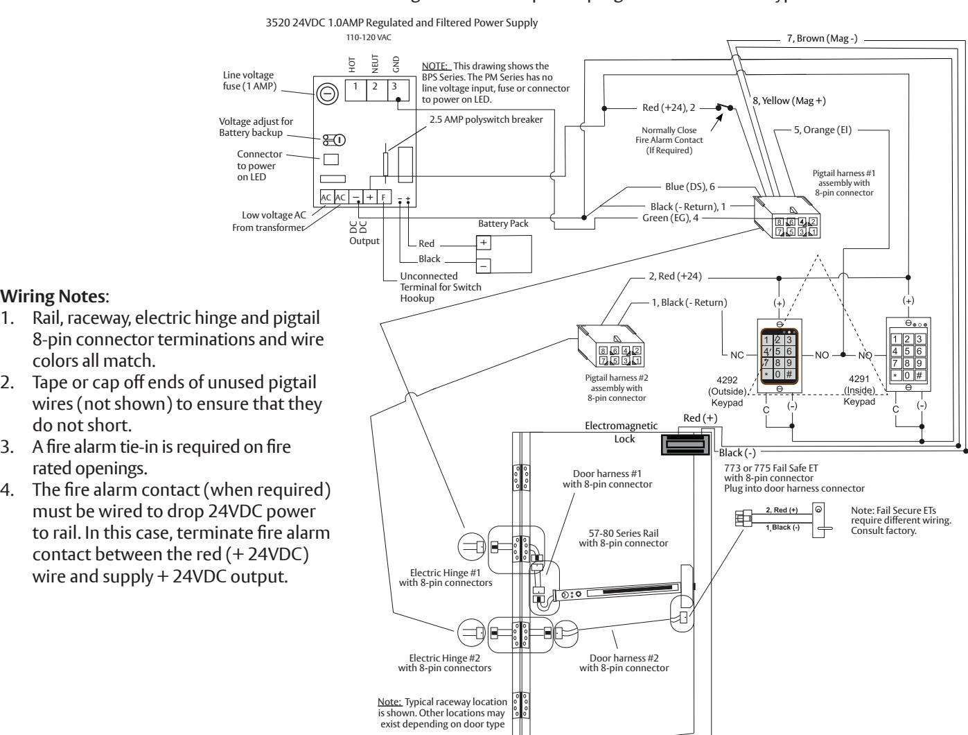
ATTENTION :
1-800-727-5477 • www.sargentlock.com
Electrifi ed Trim applications require a separate raceway and power transfer device. Installation of conductors or harnesses (by others) through the exit device rail is prohibited as it could lead to product performance issues up to and including product failure.
A7743F 1/23
Exit Device
Installation Instructions
10 Operating Instructions

a Power Up Sequence
- 1. Both insert LEDs illuminate "red" for 2 seconds while concurrently sounding buzzer for 500ms.
- 2. Both insert LEDs illuminate "green" for 2 seconds (no buzzer).
- 3. The (4) diagnostic LEDS on bottom of module illuminate for 2 seconds.
- 4. Insert LED illuminates to the switch position (armed or not armed).

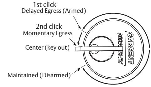
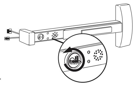
b Modes of Operation
There are three modes of operation: Armed (Delayed Egress) , Momentary Egress and Maintained Egress .
These modes are set by fully inserting a valid key and rotating it in either a clockwise or counter-clockwise direction until there is a click (detent). Note that a second click must be engaged in order to set momentary egress. To remove the key, it must be returned to its original center position.
Armed Mode
- 1. Apply power to the System; horn will sound for one second.
- 2. Both LEDs will fl ash RED, then both LEDs will fl ash GREEN.
- 3. Green (default) or Red LED on Electroguard™ insert will illuminate (See DIP switch settings section 6).
- 4. Rail assembly is armed. Latchbolt cannot be retracted by depressing the push rail for immediate egress. If rail is depressed for (min.) one second, alarm will sound.
- 5. If any of above sequence fails to function, the unit is not armed. See: Troubleshooting section

- 1. Rotate key counter-clockwise to 2nd click and return key to center position (key out).
- 2. Red (Default) or Green LED fl ashes on insert for a factory preset time of 5 seconds. (For other time selections and LED color, see Dip Switch Settings section 6). The rail assembly will disarm itself and de-energize the external magnet for this time period allowing for momentary egress.
- 3. After the factory preset time of 5 seconds, delay expires. Rail assembly re-arms itself and the external magnet is re-energized.
- 4. Unit is then in Delayed Egress Mode (or Power Up State).
Green LED

Exit Device
Installation Instructions
10 Operating Instructions (Continued)

b Modes of Operation (Continued)
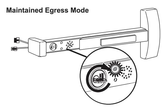
Maintained Egress Mode
- 1. Rotate key fully clockwise (one click) and return key to center position (remove key).
- 2. Red (default) or Green LED will illuminate. See Dip Switch Settings section 6 for LED color settings.
- 3. Rail assembly is disarmed allowing the device to operate as a standard exit device permitting free egress.
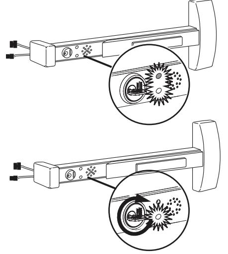
Resetting the Unit from Maintained Egress Mode to Armed Mode
- 1. Rotate key counter-clockwise and return key to center position (remove key).
- 2. Maintained Red (Default) or Green LED de-energizes and Armed Green (default) or Red LED will illuminate. See Dip Switch Settings section 6.
- 3. The rail assembly re-arms itself into the Delayed Egress Mode. External electromagnetic lock is energized. Door is locked.
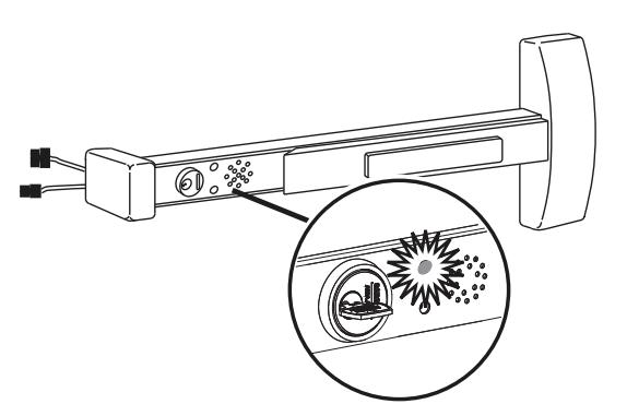
While in Delayed Egress Mode
- 1. The rail assembly is armed Green (default) or Red LED is illuminated, preventing immediate egress. See Dip Switch Settings section 6.
- 2. When the push rail is depressed for more than 1 second (nuisance delay), the alarm will sound and the Red and Green LEDs alternately fl ash. If there is no nuisance delay, alarm will sound immediately when push rail is depressed and the Red and Green LEDs will again fl ash alternately.
- 3. The alarm will continue to sound until the rail assembly is reset by inserting the key into the cylinder located on the mounting insert and rotating the key clockwise (one click) to return the unit to the armed mode.
Note : A 57-BC-80 Series device automatically resets 30 seconds after door has been closed. (Requires door position switch).
4. During fi rst 15 seconds after alarm begins, the rail assembly remains armed and external electromagnet is locked, preventing immediate egress. After 15 seconds, the rail releases the external electromagnet, allowing egress.
Note : The delayed egress time can be factory-set to 30 seconds. Local authority having jurisdiction (LHJ) prevails. Delay times may be regulated by local codes ordinances and regulations.

Exit Device
Installation Instructions

10 Operating Instructions

b Modes of Operation (Continued)
Unit Tied Into A Fire Alarm System – Optional for Non-Labeled Devices
- 1. In case of a fi re/emergency, the rail assembly will release the external electromagnet instantaneously, voiding the 15 second delay, allowing immediate egress and continuous immediate egress.
- 2. LED will be extinguished and the rail will remain unlocked.
- 3. Once the fi re alarm contact re-closes, the rail assembly automatically sets the unit into the armed mode, preventing immediate egress.
Note : Fire Alarm contact must be a normally closed (N.C.) contact.
External Inhibit Input - Optional
Used to provide remote override of the delayed egress unit when in an armed condition.
- 1. External inhibit is a normally open (N.O.) contact to common (-return).
- 2. If triggered, the unit is in an unarmed state for the duration of the time delay in the card reader, key switch or other external inhibit. Once the time delay from external inhibit device expires, the unit arms itself immediately.
Remote Reset Input - Optional
Used to provide remote reset when the delayed egress unit is in alarm and momentary egress when delayed egress unit is armed.
- 1. Remote reset input is a normally open (N.O.) contact to common (-return).
- 2. If triggered when unit is in alarm, the device is immediately reset to armed mode.
- 3. If triggered when unit is in armed mode, the device shall allow momentary egress for the time specifi ed by the DIP switch settings then return to armed mode.
Manual hex key dogging (non-fi re rated) application note:
If push bar is in the dogged (retracted) position when 24VDC power to rail is cycled (via fi re alarm/reset or temporary power outage), the device will enter hall error mode "Both Insert LEDs fl ash rapid RED and GREEN".
To clear this error mode, use the manual hex key to un-dog the push bar, ensure the push bar returns to the extended (home) position then turn the cylinder key CW to Maintained Egress mode then CCW to the center (Armed) position (or cycle 24VDC power to rail with cylinder key set to center - Armed position).
The device should clear error mode and Arm.
Exit Device
Installation Instructions
1-800-727-5477 • www.sargentlock.com
and/or patent www.assaabloydss.com/patents.

11 Troubleshooting
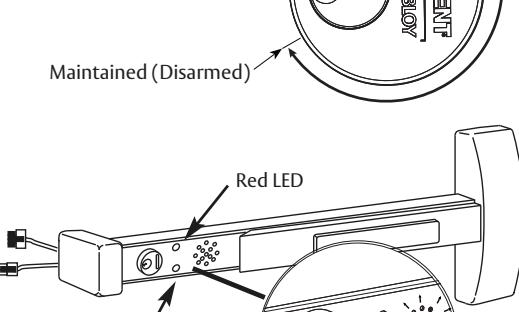
a Diagnostic and Insert LEDs
The tables below are provided to assist in the installation and troubleshooting of the 57- exit device.
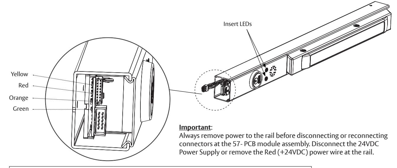
|
Diagnostic LEDs
The diagnostic LEDs are visible after install with end cap removed. |
||
|---|---|---|
| LED | Function | |
| Yellow (Latch Bolt/Rod Monitor) |
ON – Latch Bolt or Vertical Rods are retracted
OFF – Latch Bolt or Vertical Rods are extended/latched |
|
| Red (Push Rail Switch) |
ON – Rail Push Bar is depressed
OFF – Rail Push Bar is released |
|
| Orange (Door Status Switch) |
ON – Door Status Switch is open. Door is open/violated
OFF – Door Status Switch is closed. Door is closed and secure |
|
| Green (Magnet) |
ON – Rail Magnet is energized (+24VDC from main board)
OFF – Rail Magnet is de-energized |
|
|
Insert LEDs
The following table lists the status and function of the (2) Green/Red LEDs located on the rail insert. |
||
|---|---|---|
| LED | Function | |
| Green (Default) or Red ON only | Rail is Armed - Delayed Egress Mode | |
| Red (Default) or Green ON only | Rail is Disarmed – Maintained (Free) Egress Mode | |
| Red (Default) or Green "Flashing" | Rail is in Momentary Egress Mode | |
| Green and Red "Alternate," Rail Horn is ON | Rail is in violation | |
Exit Device
Installation Instructions

11 Troubleshooting (Continued)

b Rim, Mortise and Vertical Rod Exit Devices
When jumper is missing or in wrong position, the Yellow Diagnostic LED turns ON. To locate (J5) jumper, remove the Insert Assembly and Insert Assembly Plate.
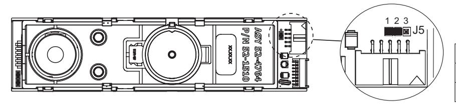
Default factory setting for 57- shown
| Function | Jumper |
|---|---|
| 57- | J5-1 & J5-2 |
| 59-STD | J5-2 & J5-3 |
- 1. When the rail is armed (in Delayed Egress Mode) and the door is closed and latched, the Green (default) or Red LED and the Green Diagnostic LED should be ON only. All other diagnostic LEDs should be OFF.
- 2. With the rail armed, depressing the rail push bar slightly will turn the Red Diagnostic LED ON. The rail should go into alarm immediately (no nuisance delay) or after being pressed in for 1 second (1-second nuisance delay). The rail will be in the irreversible alarm mode – Insert Green and Red LED fl ash and the rail horn sounds. After a standard delay of 15 seconds (or 30-second optional delay), the external magnet de-energizes and passage is allowed. The rail horn will continue to sound until the rail is reset either with a key or remotely.
- 3. When a Door Status switch is used and the door is opened the Orange Diagnostic LED will turn ON, which indicates that the door is not secure. When NOT using a Door Status switch, the Blue wire should be connected to Black (-Return). In this case, the LED will always be OFF.

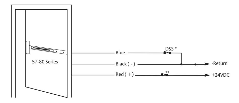
c Minimum Requirements for Arming Rail (Delayed Egress Mode)
- * To Arm 57- Rail– The Blue Door Status Switch (DSS) wire must be connected directly to the Black wire (-Return) or the contacts must be closed as shown.
- * Only these (3) wires are needed to arm rail along with the correct LBM switch and Push Rail Switch position as shown before
- ** Fire Alarm Contact (if required)
Exit Device
Installation Instructions

11 Troubleshooting (Continued)

d Symptom/Failure
*Refer to Diagnostic LED Table/Description and Minimum Requirements to Arm Rail sections.
1. Rail won't arm . Armed LED won't turn ON. Horn sounds immediately or after a delay.
When trying to arm, the rail goes into alarm immediately after momentary egress times out or after a short delay after the momentary egress times out.
Are the Yellow, Red and Orange Diagnostic LEDs OFF?
YES – Replace defective PCB module assembly.
* NO – All of these LEDs should be OFF. Troubleshoot according to which LED is ON. If any LED stays ON after troubleshooting, consult 1-800-810-WIRE
-
2. Rail won't arm
. Armed LED won't turn ON. Horn stays OFF.
- The rail is receiving an external inhibit signal.
- The Orange wire is connected to Black wire (-Return) through external device or directly.
- The rail is in fi re alarm condition.
- 3. Rail arms , but the external electromagnet is not energized when pushbar is depressed. Armed LED and Green Diagnostic LED are ON.
Troubleshoot external electromagnet or external wiring. If wires can't be repaired, consult 1-800-810-WIRE.
4. Rail arms , but will not go into alarm when depressing push bar.
Does the Red Diagnostic LED turn ON when depressing push bar?
YES – Replace defective PCB module assembly.
NO – The push rail hall switch is defective or out of activation range. If wires can't be repaired or if switch can't be adjusted (on rails which allow adjustment), consult 1-800-810-WIRE.
-
5. LEDs fl ash RED then GREEN in sequence approximately 0.25 seconds
(*Hall Error Mode). Horn and all diagnostic LEDs are off.
- Rail may or may not arm prior to this error code.
- Check harnesses are connected to controller PCBs.
- Push rail hall switch circuit defective or out of activation range. Consult 1-800-810-WIRE (9473).
- If the push bar was in the dogged (retracted) position during a 24VDC power cycle (via fi re alarm/reset or temporary power outage) this hall error mode will occur. To clear error un-dog push bar with manual hex key, ensure bar extends fully then turn cylinder key CW to Maintained Egress position then CCW to Armed (center) position (or cycle 24VDC power) to rearm device.
*If horn sounds or fl ashing sequence differs from the above; or if error mode does not clear, consult 1-800-810-WIRE (9473)
IMPORTANT: RAIL IS NOT ARMED WHEN IN THIS CONDITION!

ATTENTION :
Electrifi ed Trim applications require a separate raceway and power transfer device. Installation of conductors or harnesses (by others) through the exit device rail is prohibited as it could lead to product performance issues up to and including product failure.
A7743F 1/23