57- Delayed Action 80 Series Exit Device Installation Instructions – for devices purchased before 2005
Open the original PDF document
View PDFInstallation Instructions

80 Series Exit Device
57-Prefix Delayed Action
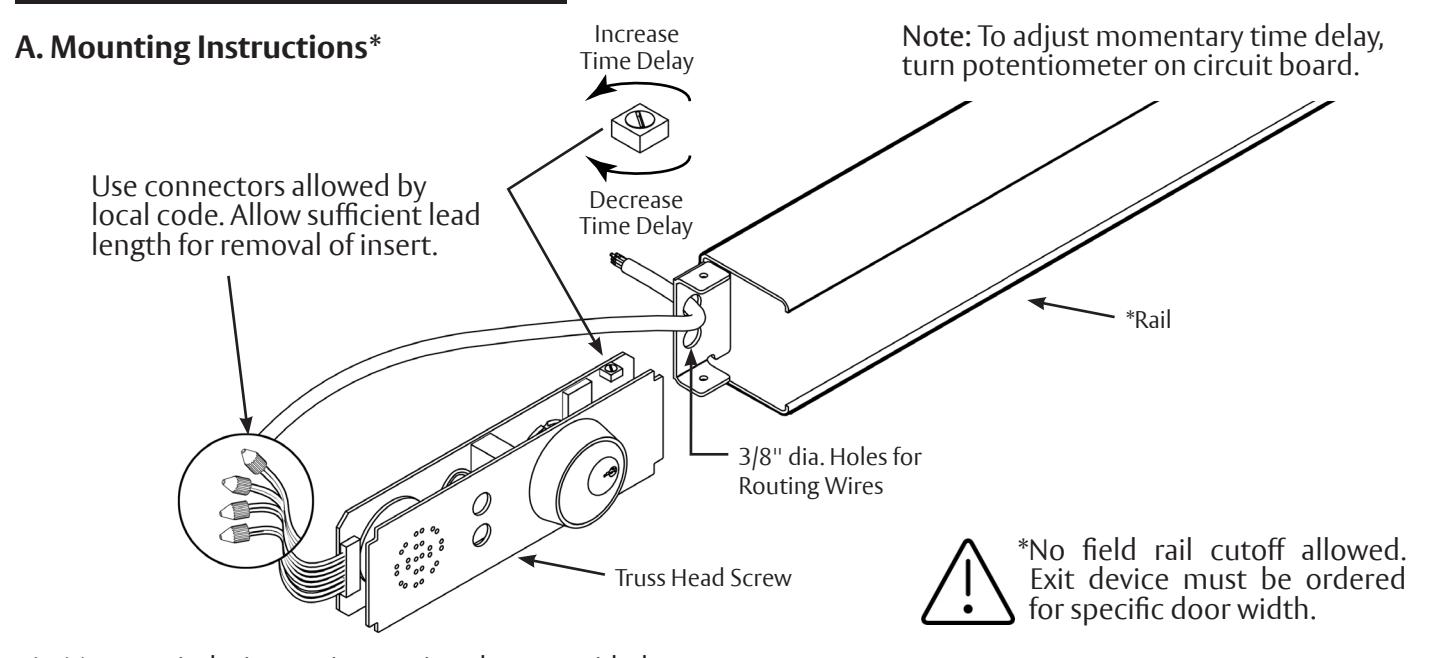
- 1. Mount exit device per instruction sheet provided.
- 2. Provide a 3/8" dia. min. raceway to allow insertion of electrical wires running between delayed action circuit board and electrical hinge.
- 3. Wiring instructions (See wiring diagram for necessary info).
B. Operating Instructions
- 1. Delayed Egress (Start-up): Rotate key fully clockwise to initiate delayed egress mode. Reverse rotation of key to remove it from cylinder. After approximately 5 seconds, the exit device will reset to the delayed egress mode. The green indicator will illuminate. The auxiliary lock (electro-magnet) will become energized, and the exit device will become armed. An attempt to egress by depressing the panic bar will initiate an irreversible process where an alarm will sound intermittently, and the red indicator will flash. The auxiliary lock will stay energized for 15 seconds in conformance with NFPA 101. In 15 seconds, the green indicator will extinguish, the red indicator will illuminate, and the auxiliary lock will de-energize, allowing egress as in conventional panic bolt exit. This condition will continue until it is reset by rotating the key clockwise to reset or initiate the delayed egress mode.
- 2. Maintained Egress Mode: Rotate key fully counterclockwise to initiate maintained egress mode. Reverse rotation of key to remove it from cylinder. The red indicator will illuminate. The auxiliary lock (electro-magnet) will de-energize indefinitely, and the exit device will function normally without triggering an alarm or requiring a delay period.

This product can expose you to lead which is known to the state of California to cause cancer and birth defects or other reproductive harm. For more information go to www.P65warnings.ca.gov.
3. Momentary Egress: Rotate key fully clockwise to initiate momentary egress. Reverse rotation of key to remove it from cylinder. The red indicator will illuminate. The auxiliary lock (electro-magnet) will de-energize for approximately 5 seconds and allow immediate egress. The exit device will automatically reset to the delayed egress mode where the green indicator will illuminate. The momentary time delay is factory-preset at approximately 5 seconds and is field-adjustable between 0-30 seconds (See Note above).
The ASSA ABLOY Group is the global leader in access solutions. Every day we help people feel safe, secure and experience a more open world.

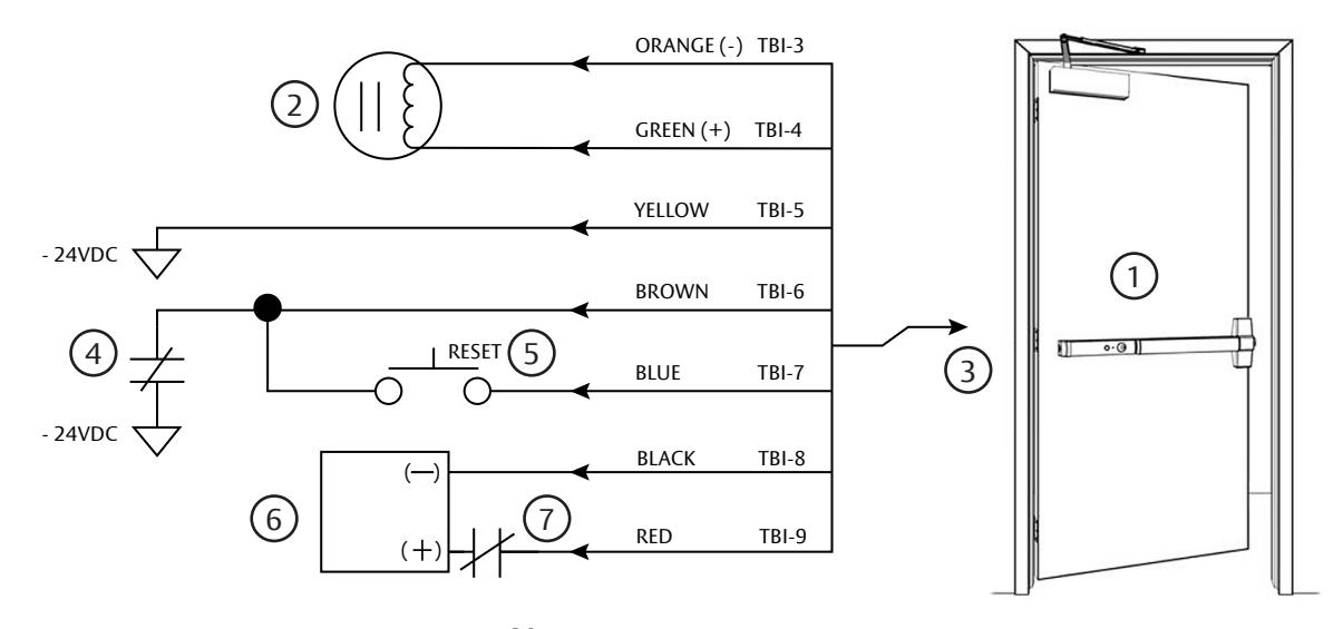
57 PREFIX DELAYED ACTION 80 SERIES EXIT DEVICE WIRING DIAGRAM
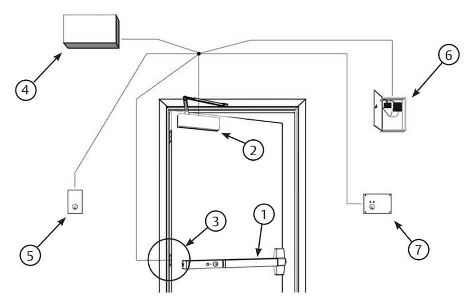
- 1. Exit device, 80 Series 57 Prefix Delayed Action
- 2. Electro-Magnetic lock, 24DC only, 250 MA (1581)
- 3. Electric hinge (4-wire minimum)
- 4. Fire alarm, n.c. contact (optional)
- 5. Fire alarm reset switch, momentary n.o. contact (optional 4371)
- 6. Power supply, 24VDC, 1.8 AMP. regulated (#3510)
- 7. Keyswitch with time delay, n.c. contact (#4284/4371LT), for remote momentary access operation (Optional)
SARGENT Manufacturing Company 100 Sargent Drive New Haven, CT 06511 USA 800-727-5477 www.sargentlock.com
Notes:
- Wires must be protected from abrasion
- For use with Class 2 circuitry only
- Colors of wires shown are of leads from the exit device, not electric hinge
- Options 4 and 5 must be used in conjunction with each other. When options are not used, connect TBI-6 and TBI-7 to TBI-8 (Neg.)
- Actuate fire alarm reset switch 5 after power-up to reset alarm
- Check local fire codes for location of reset switch 5
A6810G 8/22