55- Signal Switch for 80 Series Installation Instructions
Open the original PDF document
View PDFInstallation Instructions

Signal Switch (55- and 12-55 prefix) to ElectroLynx™ Connector System
80 Series Exit Devices
Function:
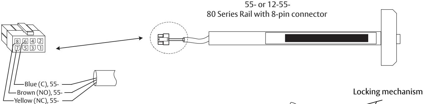
The 55- prefix signal switch monitors the touch bar. When the rail is depressed or dogged, the switch is de-activated.

Caution: Disconnect all input power before beginning installation to prevent electrical shock and equipment damage. All wiring must comply with applicable local electrical codes, ordinances and regulations. Installer must be a trained, experienced service person.
ElectroLynx Connector System Notes:
The system is designed to be installation friendly with quick connectors from the electric hinge through the door to the rail. The only wiring required is to the loose wires on the pigtail harness assembly on the frame side of the electric hinge.
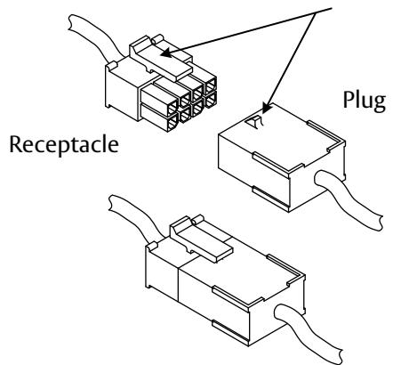
Important: The plug and receptacle connectors are designed to mate and lock together as shown in the figure. Plug the connectors into each other with the locking mechanism aligned as indicated.
Do not force connectors on any other way.

This product can expose you to lead which is known to the state of California to cause cancer and birth defects or other reproductive harm. For more information go to www.P65warnings.ca.gov.

Installation Notes:
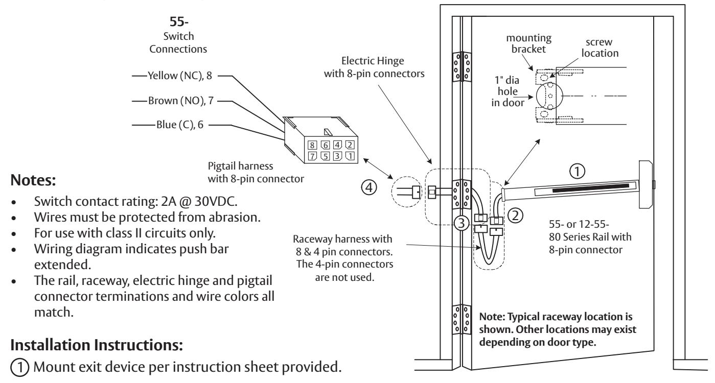
- 1. With new applications, a raceway harness with 8 and 4 pin connectors will be pre-installed inside door by ASSA ABLOY door manufacturer when specified during the ordering process. Raceway harness kits are also available for retrofit applications.
- 2. If door does not have a raceway harness with connectors, cut connectors off product, or consult factory for raceway retrofit kit.
- 3. Wiring to pigtail harness is per facility wiring requirement. The rail, raceway, electric hinge and pigtail connector terminations and wire colors all match.
55-80 Series (Signal Switch) Installation and Wiring
To insure trouble free operation, check that the push rail can be fully depressed. On vertical rod exit devices, check that the latch bolts do not go into hold back position until the push rail is fully depressed.
- 2 Plug rail connector into raceway connector. Then feed through 1" hole in door. Install rail mounting bracket with two screws supplied. Install rail insert and end cap.
- 3 Plug raceway connector into electric hinge connector, then feed through door prep. Mount electric hinge to door.
-
4 Go to (A) if wiring now. Go to (B) if wiring is to be done later.
- (A) Wire frame side wires to wires on pigtail harness as required using connectors allowed by local code. Plug pigtail harness connector into electric hinge connector. Feed harnesses through frame prep and mount electric hinge.
- (B) Plug pigtail harness connector into electric hinge connector. Feed harnesses through frame prep and mount electric hinge.
prohibited.