545 Alarm Kit Installation Instructions
Open the original PDF document
View PDFInstallation Instructions For Alarmed Exit Devices AL- 80 Series

5/15/08 Copyright © 2008 SARGENT Manufacturing. All rights reserved. Reproduction in whole or in part without the express written permission of SARGENT Manufacturing is prohibited.
|
Alarmed Exit Devices AL-80 Series
Table of Contents |
Page | |
|---|---|---|
| 1 | General Description1 | |
| 2 | Basic Installation Instructions1 | |
| 3 |
Cylinder Installation
2 |
|
| 4 | Alarmed Exit (AL-) Standard Operating Instructions3 | |
| 5 | Options3 | |
| 6 | Care of FinishBack Cover |
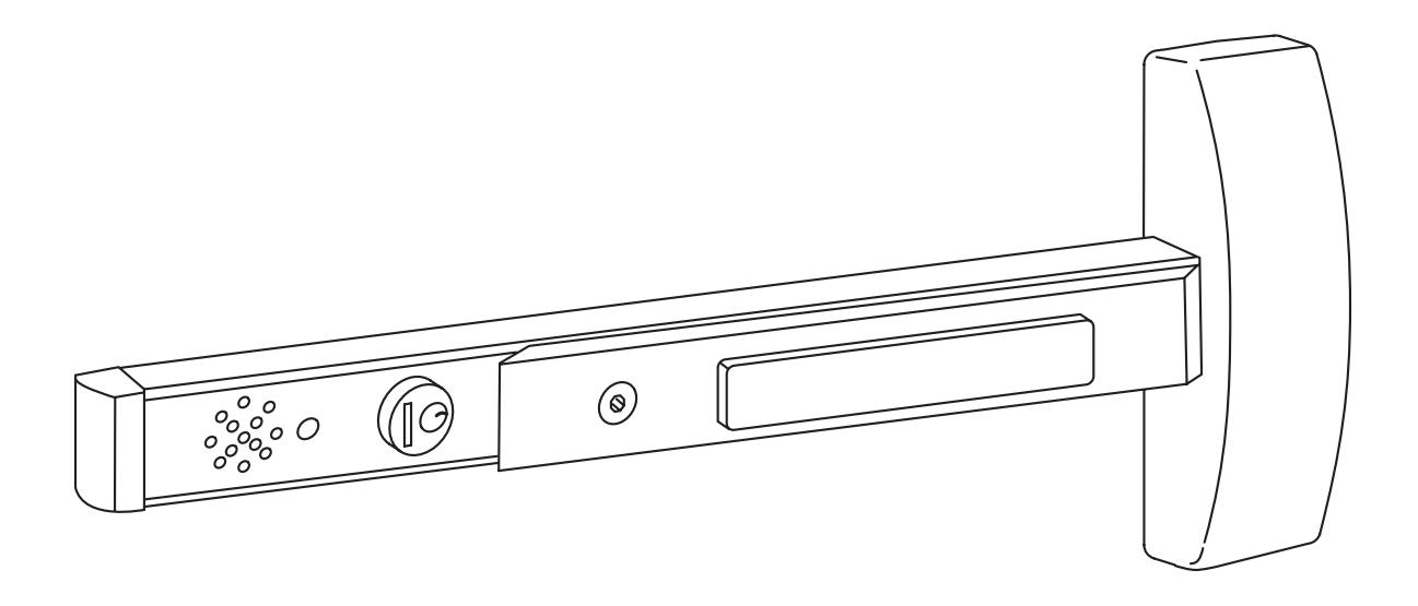
1 General Description
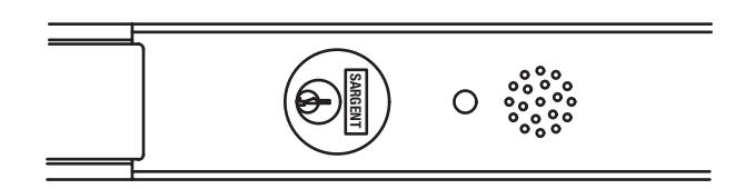
The SARGENT Alarmed Exit is designed for areas that require an alarm to sound upon exiting. Once armed, any push rail movement will activate the horn in the push rail. The horn will continue to sound for two minutes and then shut off automatically. The LED will flash indicating a violation has occurred.
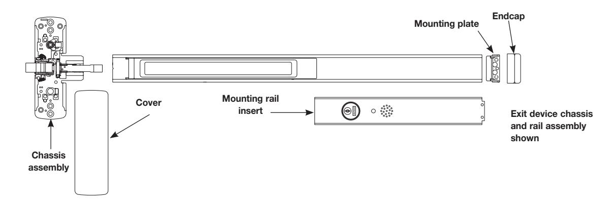
*Field cut rail assemblies are not allowed. Exit Device must be ordered from the factory for specific door width.
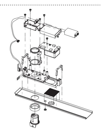
Miscellaneous Parts
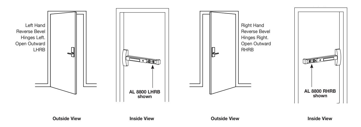
2 Basic Installation Instructions
Verify hand and bevel of door. Exit devices are always reverse bevel and are mounted on the inside of the door.
- 1. Installation must be performed by a trained experienced service person.
- 2. 9V battery operated.
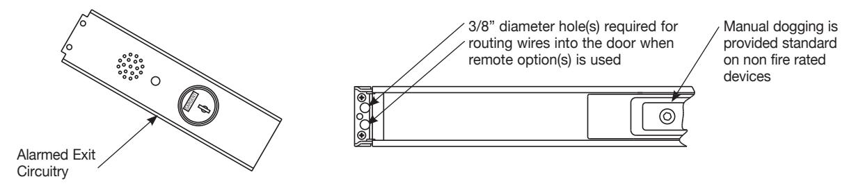
- 3. No external wires unless 546 Wiring harness used See instruction sheet (A7251B) included with kit.
3 Cylinder Installation
Page 8 Art
- 1. Prepare door according to template and Alarmed Exit instruction sheet.
- 2. Verify cylinder (size 41) is installed in rail insert with collar prior to installing exit device on door.
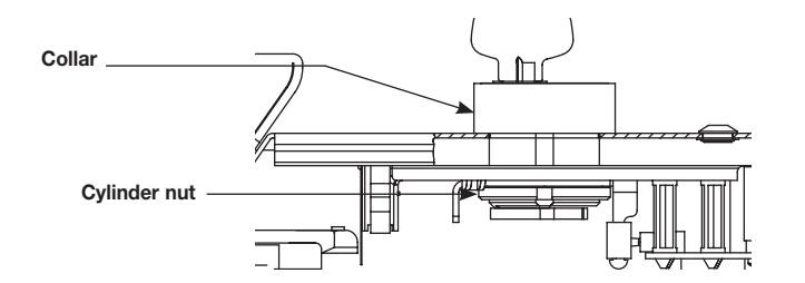
Side View. Battery holder not shown. Use caution not to damage wires when installing cylinder nut.
To Add or Remove Cylinder
1. Remove Insert Assembly from rail by sliding toward rail end.
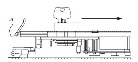
Installation and Orientation of Cylinder
Cylinder Orientation
- 2. Slide cylinder through collar into the insert as shown. NOTE: Orientation of the cylinder. Secure the cylinder with cylinder nut. Tighten firmly.
- 3. Operate cylinder and verify cam is operating switch properly.
Reproduction in whole or in part without the express written permission of SARGENT Manufacturing is prohibited.
4 Alarmed Exit (AL-) Standard Operating Instructions
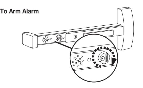
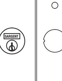
Turning key clockwise, the yellow PASSAGE LED will flash for 15 seconds (default), then a quick chirp and the ARMED green LED will flash and repeat every 30 seconds. Signal above cylinder indicates unit is armed.
NOTE: The unit is automatically armed 15 seconds after the unit is turned on. Field selectable settings listed at bottom of page.
Security/Tamper Violation
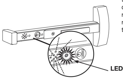
When ARMED, depressing the push rail will activate the alarm and the horn will sound and red violation LED flashes. The horn will continue to sound for 2 minutes (default). After 2 minutes the unit will reset on its own and the red LED will flash every 30 seconds until rearmed using the key. Turn the key counter clockwise to deactivate the alarm, then clockwise to rearm.
Low Battery Alert
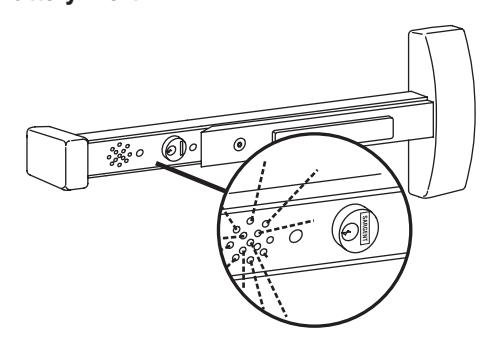
Horn chirps intermittently to indicate low battery condition. Change battery.
Battery 9 volt alkaline battery
5 Optional Settings
These field selectable switches can change the following functions:
Auto Alarm Reset
| DS3 | DS4 | Timer Reset |
|---|---|---|
| Off | Off | 2 minutes |
| Off | On | 5 minutes |
| On | Off | 10 minutes |
| On | On | Continuous* |
* Recommend 3267 power supply and 546 wiring harness
Request to Exit/Passage Time Delay
| DS1 | DS2 | Timer Reset |
|---|---|---|
| Off | Off | 7 seconds |
| Off | On | 10 seconds |
| On | Off | 15 seconds |
| On | On | 20 seconds |
Reproduction in whole or in part without the express written permission of SARGENT Manufacturing is prohibited.
Alarmed Exit Devices AL-80 Series


DS5
ON = GREEN/ARMED, RED/VIOLATION AND YELLOW/ PASSAGE (DEFAULT) OFF= GREEN/VIOLATION, RED/ARMED AND YELLOW PASSAGE.
DS6 (Needs 546 wire harness) ON= Monitor relay is enabled (will activate when rail is violated) See optional 546 wiring instructions A7251 for more information
6 Care of Finish
The following guidelines should be referenced regularly as required for proper appearance and longevity of finish:
For Finishes:
| US3 | Polished brass | US15 | Satin nickel plate |
|---|---|---|---|
| US4 | Satin brass | US20D | Dark statuary bronze- lacquered |
| US9 | Polished bronze | US26 | Polished chrome |
| US10 | Satin bronze | US26D | Satin chrome |
| US10B | Oxidized satin bronze – oil rubbed | US32 | Polished stainless steel |
| US10BL | Oxidized satin bronze – lacquered | US32D | Satin stainless steel* |
Use a mild non-abrasive detergent with damp cloth or sponge.
For the US10B Oxidized satin bronze- oil rubbed finish use a lemon oil polish with a dry cloth.
For all finishes mentioned above: Avoid abrasive cleaners, bleach solvents, steel or bronze wool.
For the US32D Satin stainless steel* finish use a plastic pad or bronze wool and avoid cleaners, solvents, bleach, and steel wool.
*To avoid discoloration and pitting:
- • keep stainless steel away from contact with other metals
- • avoid cleaning with mineral acids or chlorine products
- • avoid cleaning with abrasive products like sandpaper or steel wool
To maintain the finish:
- • frequent cleaning with a product specific for stainless will avoid discoloration and pitting
- • remove any contamination before damage occurs
- • protect with a metal polish or car wax
For installation assistance, contact SARGENT at 800-810-WIRE (9473)