539356 5300-5500 PS Arm Top Jamb Template.Rev0
Open the original PDF document
View PDFTOP JAMB INSTALLATION - PUSH SIDE - PIVOT STOP (PS) ARM APPLICATIONS
INSTRUCTION: 539356 REV.0 10-01-19
NOTES:
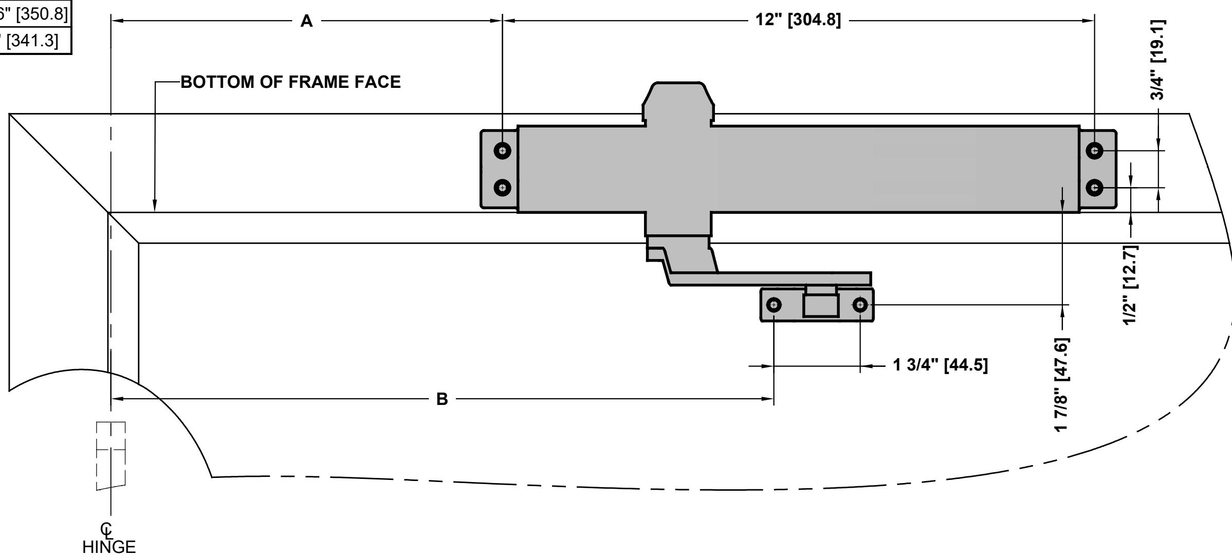
- 1. DO NOT SCALE DRAWING. LEFT HAND DOOR SHOWN.
- 2. DIMENSIONS ARE GIVEN IN INCHES [MM].
- 3. FOR DOORS WITH REVEAL OF 4 INCHES. CONSULT FACTORY FOR OTHER REVEAL DEPTHS.
- 4. MINIMUM CEILING CLEARANCE FROM BOTTOM OF FRAME FACE FOR CLOSER: 2-11/16".
OR PIVOT
- 5. SEX NUTS REQUIRED FOR UNREINFORCED OR COMPOSITE FIRE DOORS.
- 6. DOOR AND FRAME MUST BE REINFORCED PER ANSI/SDI A250.8 REQUIREMENTS MINIMUM THICKNESS RECOMMENDED FOR REINFORCEMENTS IN HOLLOW-METAL DOORS AND FRAMES: 0.067" UNLESS OTHERWISE NOTED.
- 7. HOLLOW-METAL DOORS REQUIRE CHANNEL OR BOX-TYPE REINFORCEMENT WHEN SEX NUT MOUNT IS SPECIFIED.
MACHINE SCREWS: USE #7 OR 13/64" [5.1] DRILL AND 1/4-20 TAP
WOOD DOOR/FRAME SCREWS: USE 5/32" [4] DRILL
SEX NUTS:
USE 3/8" [9.5] DRILL (CLOSER TO DOOR)

PDQ Manufacturing 2230 Embassy Dr. Lancaster, PA 17603 833-273-7832 833-2 PDQTECH www.pdqlocks.com
5300/5500 DOOR CLOSER MODELS TOP JAMB INSTALLATION - PUSH SIDE - PIVOT STOP (PS) ARM APPLICATIONS

- 1. Confirm this sheet is correct for your product and application.
- 2. Read the complete instruction sheet before starting installation.
- 3. Incorrectly installed or adjusted door closers can cause personal injury or property damage.
- 4. To ensure safe operation, door closers should be examined and serviced regularly.

NOTES:
- 1. See reverse side of this sheet to machine door & frame.
- 2. Dimensions based on 4-1/2" x 4-1/2" full mortise butt hinges with 5/8" stop and 1/8" door gap.
- 3. Confirm door & frame are properly reinforced.
- 4. Sex nuts required for un-reinforced or composite fire doors.
- 5. Do not install closer on the exterior (weather) side of building.

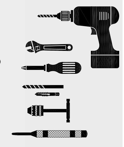
TOOLS REQUIRED:
- 1. Power drill
- 2. 10mm box/combo wrench
- 3. Phillips screw driver
- 4. #7 or 13/64" drill bit and 1/4-20 tap (metal screws)
- 5. Tap handle
- 6. 5/32" drill bit (wood screws)
- 7. 3/8" drill bit (sex nuts)
- 8. Center punch

PREPARE DOOR AND FRAME:
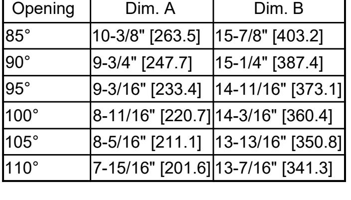
- 1. Determine proper opening angle.
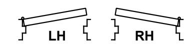
- 2. Determine door hand (LH or RH).
- 3. Using template (see reverse side), mark holes on door & frame.
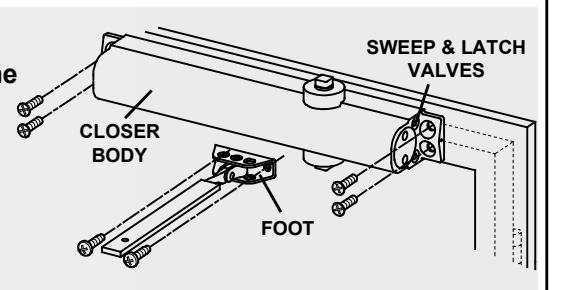
INSTALL CLOSER AND ARM:
- 1. Attach closer body to frame face. Sweep and latch valves point toward hinge.
- 2. Attach foot to door.
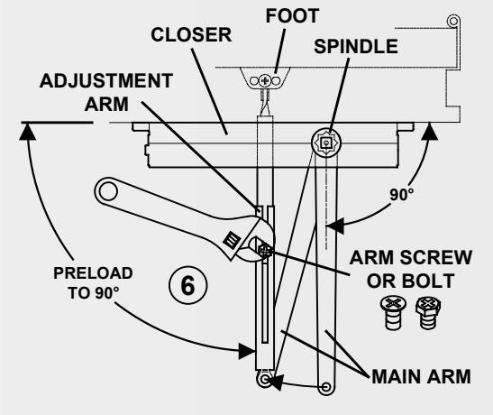
- 3. Secure main arm to closer spindle 90° to door/frame.
- 4. Connect adjustment arm with foot assembly: Rotate main arm until adjustment arm is 90° to door & frame. Tighten arm screw or bolt.
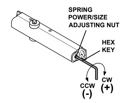
ADJUST SPRING POWER:
1. Use 4 mm hex key provided to adjust to size on chart. Clockwise (CW) turns increase spring power (+). Counter-clockwise (CCW) turns decrease spring power (-).
5300/5500 Series closers can be adjusted to meet ADA Barrier Free (BF) applications. Compliance with ADA/BF requirements may result with door not fully closing and latching. Check with local AHJ. Closer size may vary due to site conditions.
| DOOR WIDTH | APPROX. | ||
| SIZE | INTERIOR | EXTERIOR | 360° TURNS |
| BF | 5 LBF ON 36" | -8 (CCW) | |
| 1 | 32" [812.8] | 28" [711.2] | -6 (CCW) |
| 2 | 36" [914.4] | 32" [812.8] | -4 (CCW) |
| 3 | 42" [1066.8] | 36" [914.4] | 0 (PRESET) |
| 4 | 48" [1219.2] | 42" [1066.8] | +5 (CW) |
| 5 | 54" [1371.6] | 48" [1219.2] | +9 (CW) |
| 6 | 58" [1473.2] | 54" [1371.6] | +12 (CW) |
INSTRUCTION: 539356 REV.0 10-01-19
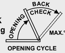
CONTROL ADJUSTMENTS:
■ CRITICAL: For closer longevity, BACKCHECK must be adjusted to significantly slow opening of door before arm bottoms on stop.
Closing time of 3-7 seconds is typical. More time may be needed for ADA/BF access. Clockwise (CW) = SLOWER. Counter-clockwise (CCW) = FASTER. DO NOT REMOVE VALVES
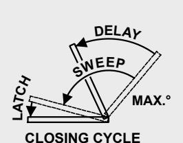
- 1. Use hex key provided.
- 2. Adjust SWEEP (closing max.°- 10°).
- 3. Adjust LATCH (closing 10°-0°).
- 4. Adjust BACKCHECK resistance (opening 70°- max.°). DO NOT COMPLETELY CLOSE VALVE
- Adjust (optional) DELAYED ACTION (closing max.°-70°); Provides additional hesitation for access (ADA/BF) through door.


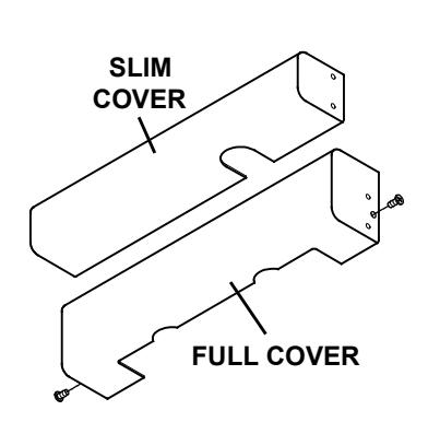
INSTALL COVER:
- 1. Slip cover over closer until flush with door face.
- Wide Cover Orient cover so cutout is at bottom of closer body. Secure to closer with screw on each end. Narrow Cover - Cover will snap into slots on closer body. Install dust cap over top closer pinion.
NOTE: Sweep, latch, backcheck, and optional delayed action valves are all accessible after cover installation.

PDQ Manufacturing 2230 Embassy Dr. Lancaster, PA 17603 833-273-7832 833-2 PDQTECH www.pdglocks.com