5300 Series Alarmed Exit Devices Installation Instructions
Open the original PDF document
View PDFInstallation Instructions

5300 Series
Alarmed Exit Devices

This product can expose you to lead which is known to the state of California to cause cancer and birth defects or other reproductive harm. For more information go to www.P65warnings.ca.gov.

Disconnect all input power before beginning installation to prevent electrical shock and equipment damage.
5300 Series
Alarmed Exit Devices
Installation Instructions

| TOC | Table of Contents | |
|---|---|---|
| 1 | General Description 3 | |
| 2 | Contents 3 | |
| a | Package Contents 3 | |
| b | Miscellaneous Parts 4 | |
| 3 | Dip Switch (SW-2, 6-position) 4 | |
| 4 | AL - Circuit Board 5 | |
| 5 | Installation Instructions 6 | |
| 6 | Apply Rail Assembly 7 | |
| 7 | Cylinder Installation 7 | |
| a | Door Preparation 7 | |
| b | Add or Remove Cylinder 8 | |
| c | Installation and Orientation of Cylinder 8 | |
| 8 | Alarmed Exit (5300) Standard Operating Instructions 9 | |
| a | Arm Alarm 9 | |
| b | Security/Tamper Violation 9 | |
| c | Low Battery Alert 9 | |
| 9 | Optional Features | 10 |
Installation Instructions

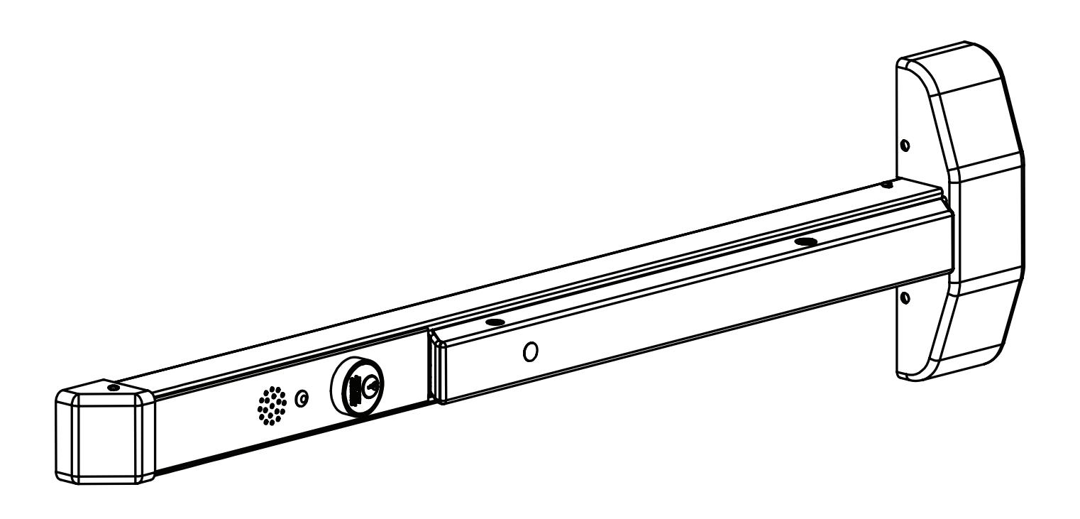
1 General Description
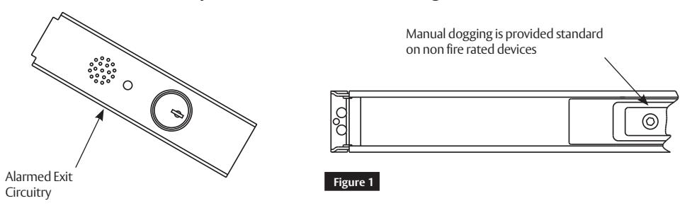
The SARGENT Alarmed Exit is designed for areas that require an alarm to sound upon exiting. Once armed, any push rail movement will activate the horn in the push rail. The horn will continue to sound for two (2) minutes and shut off automatically. The LED will flash, indicating a violation has occurred.
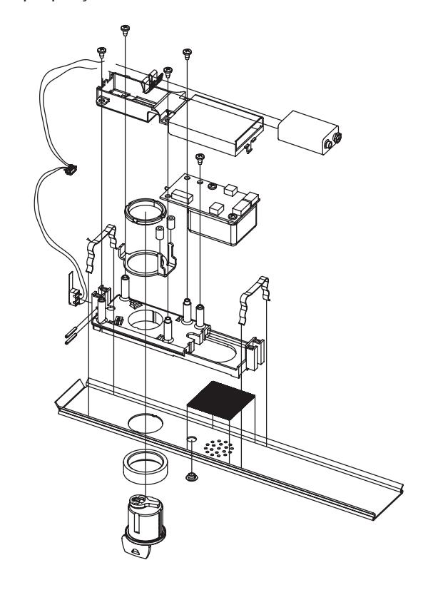
2 Contents
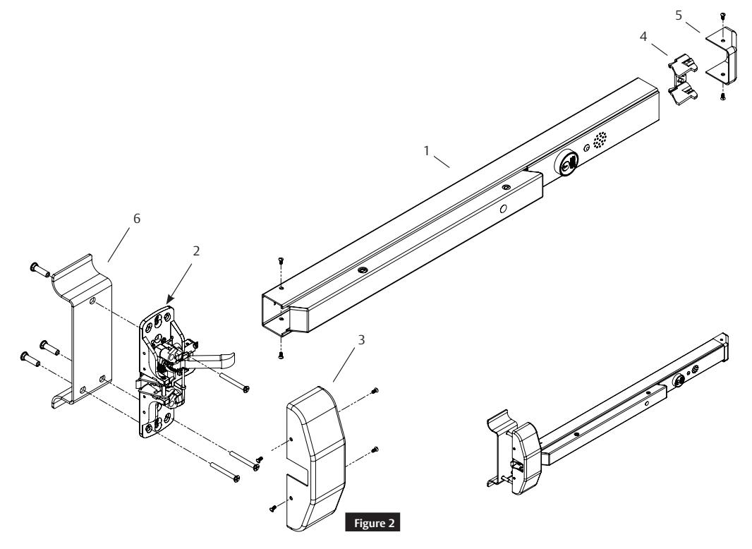
a Package Contents
|
Figure 2
Description |
||||
|---|---|---|---|---|
| 1 | Mounting Rail, Wilde Stile | |||
| 2 | Chassis Assembly (Wide) | |||
| 3 | 5300 Cover, Chassis | |||
| 4 | End Cap Bracket | |||
| 5 | End Cap | |||
| 6 | Pull (Sold Separately) | |||
Installation Instructions

2 Contents (cont.)
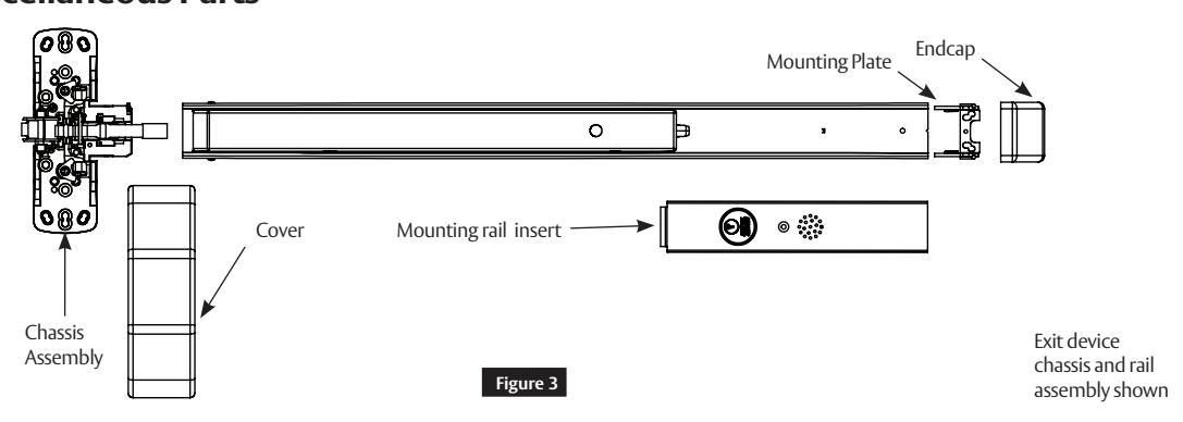
b Miscellaneous Parts
3 Dip Switch (SW-2, 6-position)
Factory settings shown.
- 1. DS-1 = OFF, DS-2 = OFF REX / Passage Delay (set to 7 seconds).
- 2. DS-3 = OFF, DS-4 = OFF Automatic Alarm Reset (set to 2 minutes).
- 3. DS-5 = ON Selects LED color (Armed = Green, Violation = Red, Passage = Yellow).
- 4. DS-6 = ON Monitor Relay is enabled (will activate when rail is violated).
Installation Instructions

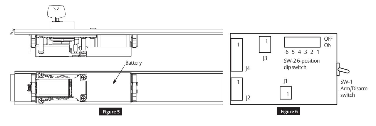
4 AL - Circuit Board
Printed Circuit Board:
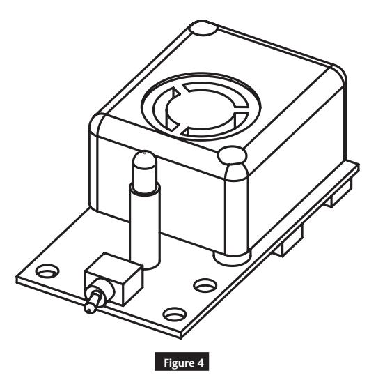
Note
SW-1, Arm/Disarm Switch shown in ON (armed) position.
Insert with circuit board:
Installation Instructions

5 Installation Instructions
- These instructions are for the 5300 Series exit device, which is designed for areas requiring field selectable time delay and automatic alarm reset options.
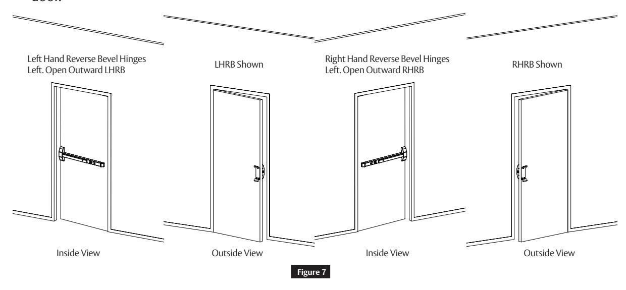
- Verify hand and bevel of door. Exit devices are always reverse bevel and are mounted on inside of door.
- 5. Installation must be performed by a trained and experienced service person.
- 6. 9V battery operated.
- 7. No external wires.
Note:
For retrofit applications, refer to retrofit instructions.
Installation Instructions

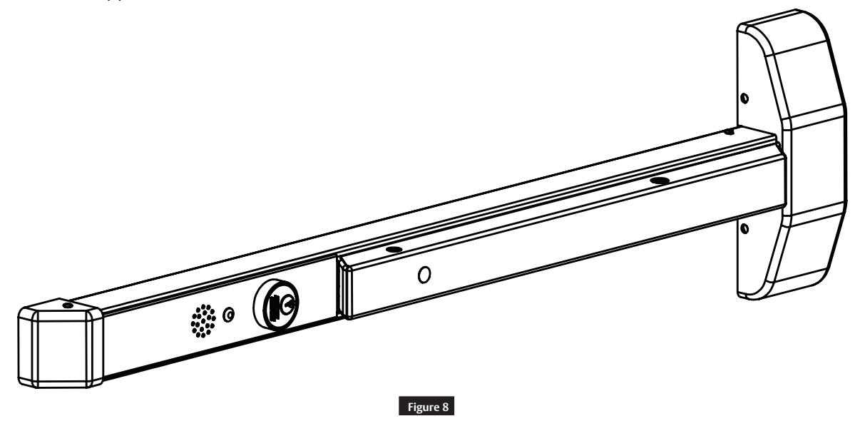
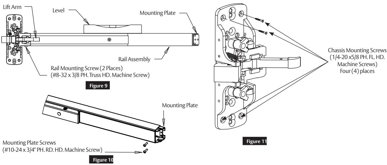
6 Apply Rail Assembly
- 1. Depress lift arm into rail assembly and slide rail onto chassis.
- 2. Attach rail assembly to chassis with two (2) #8 truss head machine screws. Do not tighten screws (Figure 9 ).
- 3. Secure chassis to door with four (4) #10 flat head screws. (Figure 8)
- 4. Level rail.
- 5. Place mounting plate tight against rail and attach to door with two (2) #10 round head screws.
- 6. Tighten all screws securely ( Figure 10) .
7 Cylinder Installation
a Door Preparation
- 1. Prepare door according to template.
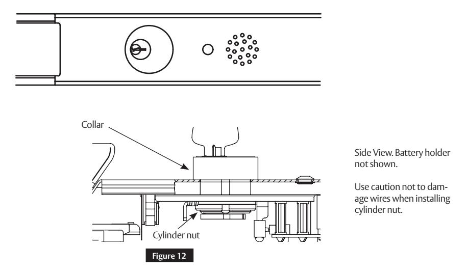
- 2. Verify size 41 cylinder is installed in rail insert with collar prior to installing exit device on door.
NOTE: Use caution not to damage wires when installing cylinder nut.
Installation Instructions

7 Cylinder Installation (cont.)
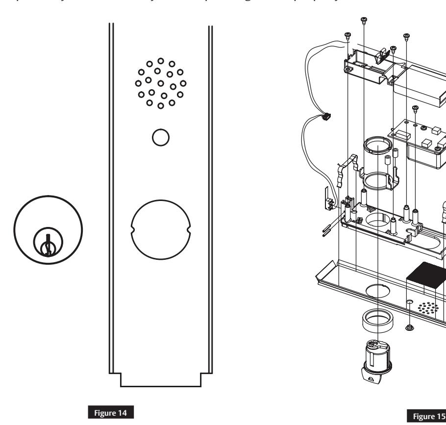
b Add or Remove Cylinder
3. Remove insert assembly from rail by sliding toward rail end.
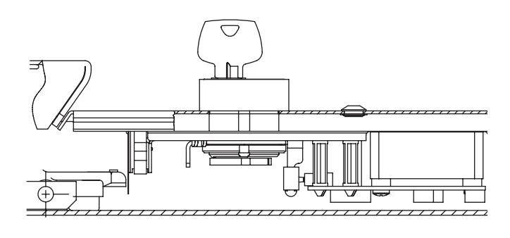
Figure 13
c Installation and Orientation of Cylinder
- 1. Slide cylinder through collar into insert as shown.
- 2. Note orientation of cylinder.
- 3. Secure cylinder with cylinder nut, tightening firmly.
- 4. Operate cylinder and verify cam is operating switch properly.
Installation Instructions

8 Alarmed Exit (5300) Standard Operating Instructions
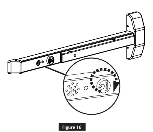
a Arm Alarm
Turn key clockwise. Yellow PASSAGE LED will flash for 15 seconds (default), then a quick chirp and ARMED green LED will flash and repeat every 30 seconds. Signal above cylinder indicates unit is armed.
NOTE: Unit is automatically armed 15 seconds after it is turned on. Field selectable settings listed at bottom of page.
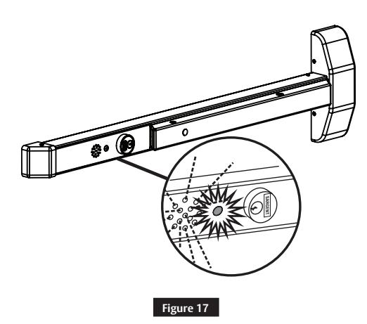
b Security/Tamper Violation
When ARMED, depressing the push rail will activate alarm. Horn will sound and red violation LED will flash. The horn will continue to sound for two (2) minutes (default). After two (2) minutes, unit will reset on its own and red LED will flash every 30 seconds until rearmed using the key. Turn key counter-clockwise to deactivate alarm. Turn key clockwise to rearm alarm.
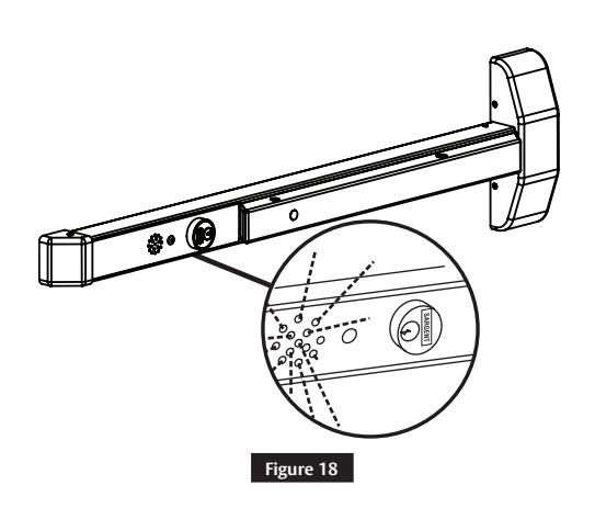
c Low Battery Alert
Horn chirps intermittently to indicate low battery condition. Replace 9-volt alkaline battery.
Installation Instructions

9 Optional Features
Once power is connected, turn key clockwise to activate alarm. A time delay of 7, 10, 15 or 20 seconds initiates prior to rail going into an armed state. This allows individualized alarm setting. LED will flash yellow during this time.
Horn will chirp one (1) time. LED will flash green and repeat every 30 seconds to indicate unit is armed. Once armed, depress push bar to sound alarm. Rail alarm will sound until disarmed using one (1) of the following methods:
- 1. Rail cylinder key
- 2. Automatic reset (after optional field settable time delay of 2, 5 or 10 minutes)
LED will flash red every 30 seconds to indicate rail has been violated and will continue to flash red until unit is reset manually. If battery powered and low battery voltage is detected, horn chirps quickly and repeats every 10 seconds until battery is replaced.
These field selectable switches can change the following functions:
| DS3 | DS4 | Timer Reset | DS1 | DS2 | ||
|---|---|---|---|---|---|---|
| Off | Off | 2 minutes | Off | Off | ||
| Off | On | 5 minutes | Off | On | ||
| On | Off | 10 minutes | On | Off | ||
| On | On | Continuous | On | On |
Auto Alarm Reset Request to Exit/Passage Time Delay
| DS3 | DS4 | Timer Reset | DS1 | DS2 | Timer Reset |
|---|---|---|---|---|---|
| Off | Off | 2 minutes | Off | Off | 7 seconds |
| Off | On | 5 minutes | Off | On | 10 seconds |
| On | Off | 10 minutes | On | Off | 15 seconds |
| On | On | Continuous | On | On | 20 seconds |
5300 Series
Alarmed Exit Devices
Installation Instructions

Page intentionally left blank.
SARGENT Manufacturing Company 100 Sargent Drive New Haven, CT 06511 USA 800-727-5477 www.sargentlock.com