5200 Track Arm Installation Instructions – I-CL00578-Rev-5
Open the original PDF document
View PDF

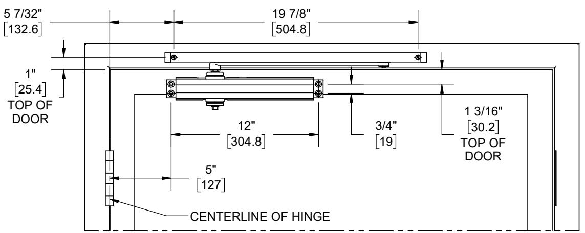
PULL SIDE APPLICATION (RIGHT HAND SHOWN) 120 DOOR PREP
NOTES:
increments of 1/2" until desired angle is achieved. - If you would like a smaller swing angle, move the Hold Open Stop or Stop Only away from the pivot hinge in
Installation Sequence:
- 1. Use door prep dimensions above to locate holes on door and frame. Drill 1/8" pilot holes for the self tapping screws.
- 2. Fasten closer body to the door with power adjustment port away from hinge.
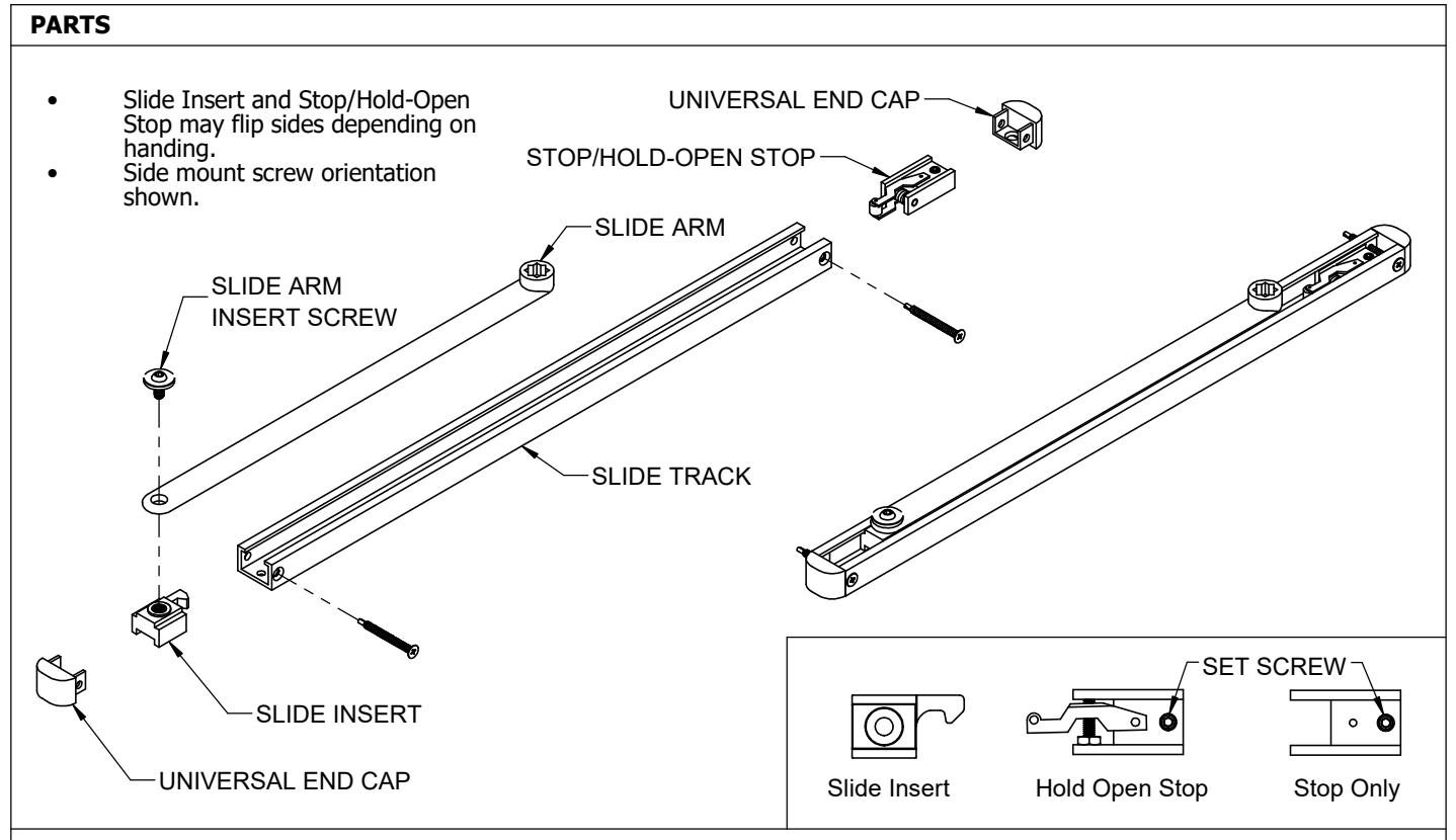
- 3. Fasten slide track to the frame with open side facing down and stop/hold-open end toward the hinge edge of door.
- 4. Place the slide arm on the pinion shaft of closer so the arm is positioned at a 45 degree angle out from the door and fasten it with the screw.
- 5. To properly preload closer, push the arm so it is parallel with the door and fasten the other end of slide arm to the track by screwing it to the slide insert with the shoulder screw.
- down with the set screw. 6. Open door to required opening angle. Slide the stop/hold-open stop against the slide insert and tighten it
- 7. Determine the door width and adjust the spring power by referencing closer adjustments on page 4.

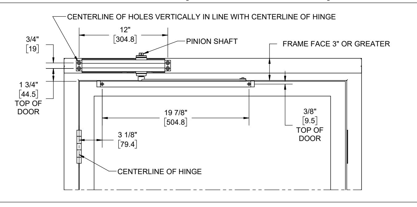
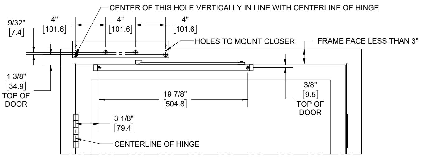
TOP JAMB MOUNT APPLICATION 120 DOOR PREP [STANDARD AND 5918 PLATE SHOWN]
NOTES:
- Requires 5918 drop plate when the head frame face is less than 3"
- hinge in increments of 1/2" until desired angle is achieved. - If you would like a smaller swing angle, move the Hold Open Stop or Stop Only away from the pivot
Installation Sequence:
- 1. Use door prep dimensions above to locate holes on door and frame. Drill 1/8" pilot holes for the self tapping screws.
- 2. If using the 5918 plate, fasten it to the frame in orientation shown above.
- 3. Fasten closer body to the frame/5918 plate with power adjustment nut facing towards the hinge edge of the door.
- 4. Fasten slide track to door face with open side facing up and with stop/hold-open end toward the hinge edge of the door.
- 5. Use a wrench to rotate the top of the pinion shaft 45 degrees clockwise. Place the slide arm on the bottom of the pinion shaft so it is parallel with the door aiming away from the hinge edge.
- 6. Secure the arm with the screw. If you let go of the arm, it should push against the door.
- 7. Secure other end of slide arm to the track by screwing it to the slide insert with the shoulder screw.
- 8. Open door to required opening angle. Slide the stop/hold-open stop against the slide insert and tighten it down with the set screw.
- 9. Determine the door width and adjust the spring power by referencing closer adjustments on page 4.

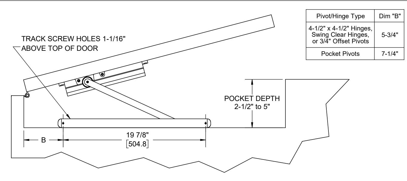
POCKET DOOR APPLICATION 90 OPEN DOOR INTO POCKET
Installation Sequence:
- 1. Use template above to locate mounting holes on pocket wall and mount closer according to pull side application template. Drill 1/8" pilot holes for the self tapping screws.
- 2. Fasten closer body to door with power adjustment port away from hinge.
- 3. Orientate the track with the open side facing down and stop/hold-open stop end away from the hinge edge of the door. Slide end caps on, orientated with countersink visible. Fasten slide track to pocket wall face.
- 4. Secure the slide arm to the track by screwing it to the slide insert with the shoulder screw. Door must remain in closed position for the following assembly steps.
- 5. Swing arm toward closer and rest the hub of the arm on top of the closer pinion. Place a wrench on the bottom pinion of the closer and rotate away from the hinge (approx. 30 degrees). When the cutout of the arm hub and the pinion line up, slide the arm hub down over the pinion and secure tightly with the screw. This pretensions the closer arm.
- stop/hold-open stop towards the hinge about 1/2" and tighten it down with the set screw. 6. Loosen the stop/hold-open stop and put it next to the slide insert. Open the door to required opening angle pushing the stop/hold-open stop to the correct location. Close the door. Now slide the
- 7. Determine door width, adjust spring power of closer by referencing closer adjustments on page 4.

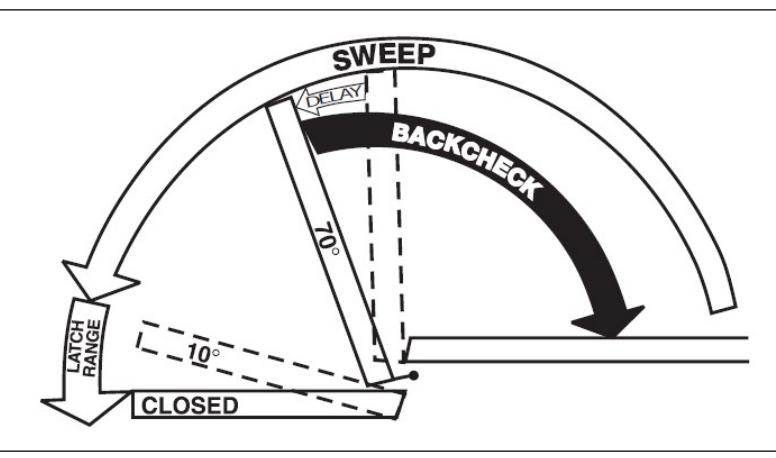
ADJUSTMENTS (USE 5/32" HEX WRENCH FOR THESE ADJUSTMENTS)
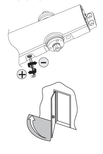
SWEEP SPEED
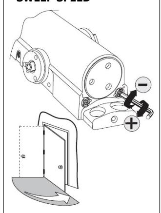
Note: Adjust closing time speed to between 3 and 7 seconds from 90° to 0°. Greater closing times may be required for elderly or handicapped.
LATCH SPEED
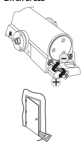
Adjust latch speed so door completely closes and latches.
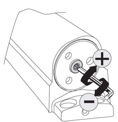
BACKCHECK
Adjust backcheck accordingly to prevent excessive opening speed.
OPTIONAL DELAY ACTION
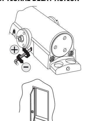

obtain desired delay time.
SPRING POWER ADJUST (SIZING IN ACCORDANCE TO BHMA/ANSI 156.4)
*Use 5/32" Hex Wrench
TABLE OF SIZES
Closer is shipped set to size 3. To change the closer size, use a hex wrench to rotate the spring power adjust. Follow the chart to make the correct numbers of 360° turns to set the closer size appropriately for the door application.
The number of turns is an approximation and does not account for environmental or door hardware affects.
Approx. 4 turns to increase/decrease one size. cw=clockwise ccw = counterclockwise
Exterior (and Vestibule) Door Width
| =/// | 101 (4114 | 1 000.00 |
.,
|
||
|---|---|---|---|---|---|
| Minimum Door Width 24" | |||||
| 24" | 30" | 36" | 42" | 48" | |
| (610mm) | (762mm) | (914mm) | (1067mr | n)(1219mn | ո) |
| Regular Arm | Size 3 | Size 4 | Size 5 | Size 6 |
| & Top Jamb | (0) | (4cw) | (8cw) | (12cw) |
| Parallel | Size 3 | Size 4 | Size 5 | |
| Arm | (4cw) | (8cw) | (12cw) |
| Interior Door Width |
|---|
| 24" | 30" | 34" | 38" | 48" | 54" | 60" |
|---|---|---|---|---|---|---|
| (610mm) | (762mm) | (864mm) | (965mm) | (1219mm) | (1372mm) | (1524mm) |
Size 3 Size 2 Size 4 Size 5 Size 6 Regular Arm Size 1 & Top Jamb (8ccw) (4ccw) (0)(4cw) (8cw) (12cw) Size 1 Size 2 Size 4 Size 5 Size 3 Parallel (4ccw) (0)(4cw) (8cw) (12cw) Arm
ADJUSTMENT DIAGRAM