5200 Series DE Track Arm I-CL00581-Rev3
Open the original PDF document
View PDF

Installation Instructions I-CL00581
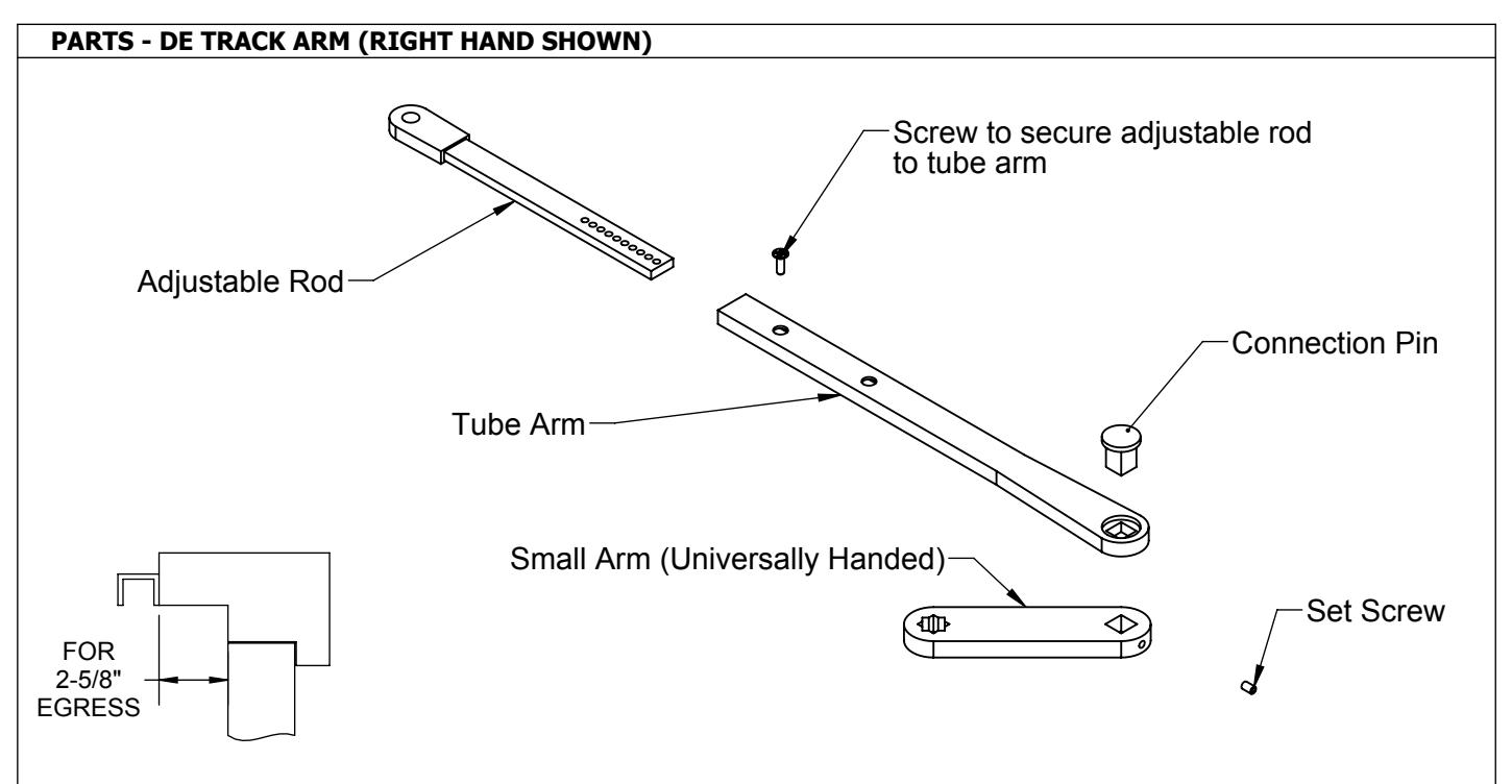
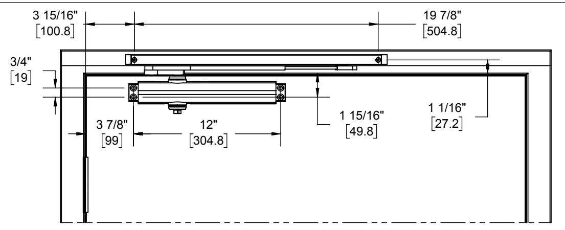
INSTALL DE TRACK ARM - PULL SIDE APPLICATION (RIGHT HAND SHOWN) 120° TEMPLATE
NOTE: IF USER WISHES TO HAVE A LESSER SWING ANGLE, SIMPLY MOVE HOLD OPEN STOP OR STOP ONLY AWAY FROM THE PIVOT HINGE IN INCREMENTS OF 1/2" UNTIL DESIRED ANGLE IS ACHIEVED.
Installation Sequence:
- Use template above to locate mounting holes on door and frame. Drill 1/8" pilot holes for the self tapping screws.
- 2. Determine door width, adjust spring power of closer by referencing closer installation instructions.
- 3. Fasten closer body to door with power adjustment nut away from hinge.
- Fasten slide track to frame face with open side facing down and with hold open stop end toward 4. hinge edge of door.
- 5. Place slide arm on pinion shaft of closer at preload of 45 degrees out from door face.
- 6. 7. Secure arm with arm washer and arm screw. Push arm towards door to pretension closer then secure other end of slide arm to track by screwing it to the slide insert. Open door to required opening angle. Then slide stop only/hold open stop up against slider insert and tighten down the stop only/hold open stop via set screw.
REV: 3 REV DATE: 9/16/2022 Page 1 of 4

Installation Instructions I-CL00581
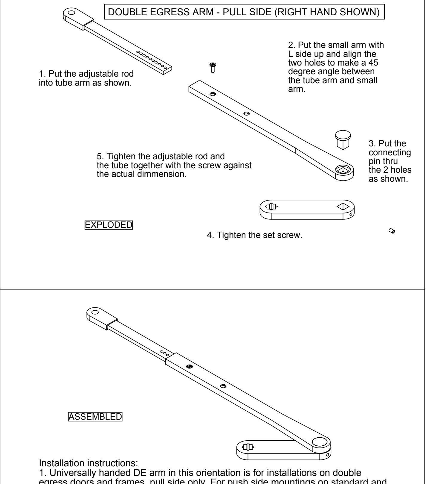
egress doors and frames, pull side only. For push side mountings on standard and double egress frames, see page 4.
2. Reference instructions above for arm assembly. Right hand shown. For left hand simply mirror the short arm 45 degrees to the opposite side of main arm.
3. Reference instructions on page 1 for specific mounting with closer and track.
REV: 3 REV DATE: 9/16/2022 Page 2 of 4

Installation Instructions I-CL00581
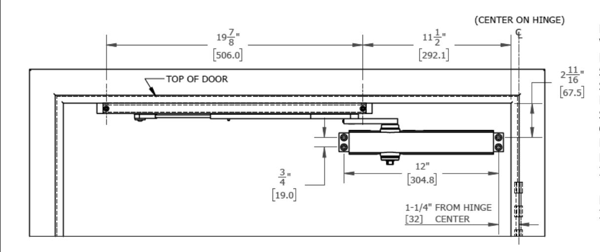
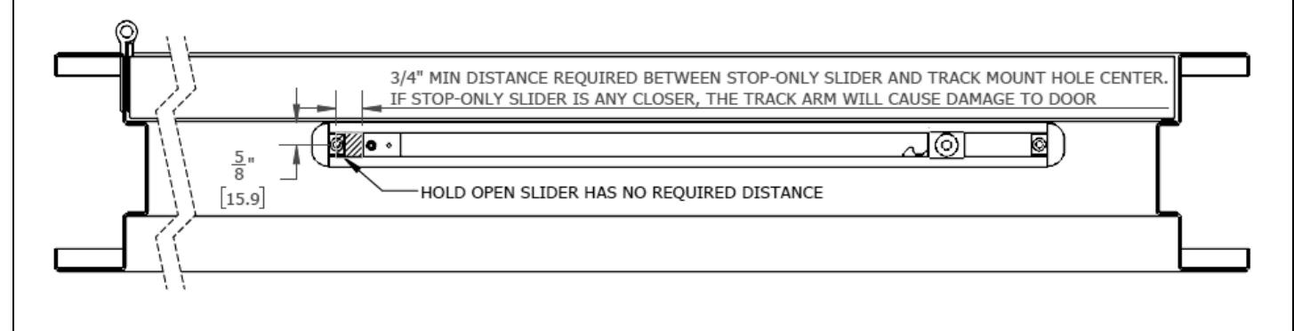
INSTALL DE TRACK ARM – PUSH SIDE APPLICATION (RIGHT HAND SHOWN) TEMPLATE 100° MAX OPENING FOR STOP ONLY 95° MAX OPENING FOR HOLD OPEN STOP
NOTE: IF USER WISHES TO HAVE A LESSER SWING ANGLE, SIMPLY MOVE HOLD OPEN STOP OR STOP ONLY AWAY FROM THE PIVOT HINGE IN INCREMENTS OF ½" UNTIL DESIRED ANGLE IS ACHIEVED.
Installation Sequence:
- 1. Use the template above to locate mounting holes on door and frame. Drill 1/8" pilot holes for the self-tapping screws.
- 2. Determine door width, adjust spring power of closer by referencing closer installation instructions.
- 3. Fasten closer body to door with speed regulating valves toward the lock stile.
- 4. Fasten slide track to frame soffit with open side facing down, and the stop/hold-open stop at the hinge side of the track.
- 5. With a wrench, preload the pinion with a 45 degree turn toward the hinge stile. Then place the arm onto the pinion. Track end of arm will naturally press against the door.
- 6. Secure arm with arm washer and arm screw to the closer pinion.
- 7. Pull arm to align with the slider, then secure slider end of arm to the slider. Open door to required opening angle, then slide the stop/hold-open stop either up against slider, or to lock position with slider, and tighten down via the set screw. See below for positioning.
REV: 3, REV DATE: 9/16/22 Page 3 of 4

Installation Instructions I-CL00581
Installation Instructions:
- 1. Universally handed DE arm in this orientation is for installations on standard or DE doors and frames, push side only. For DE arm orientation in pull side mountings, see page 2.
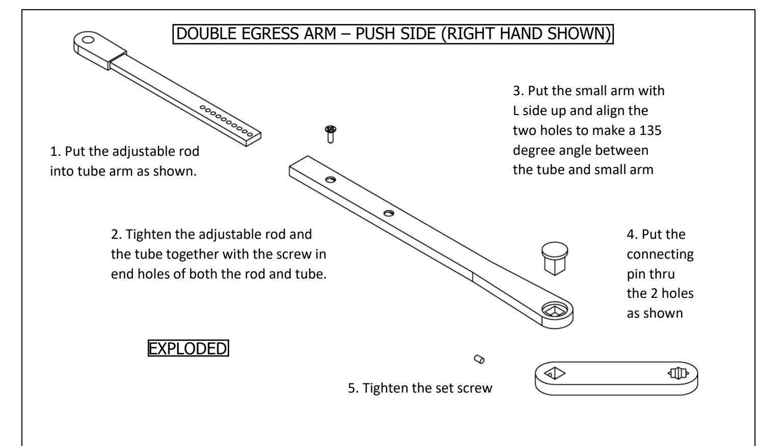
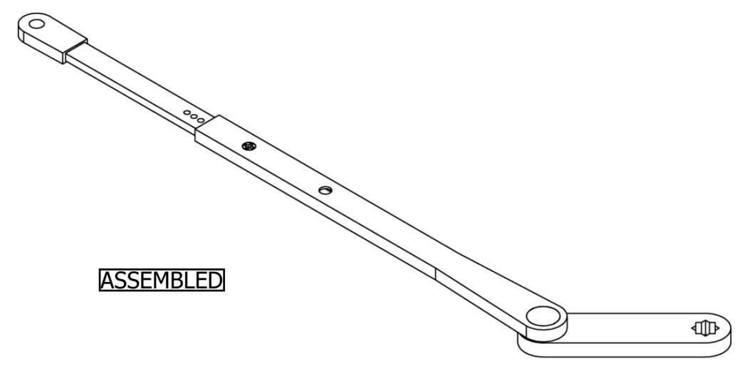
- 2. Reference instructions above for arm assembly. Right hand shown. For left hand, simply mirror the short arm 135 degrees to the opposite side of main arm.
- 3. Reference instructions on page 3 for specific mounting with closer and track push side.
REV: 3, REV DATE: 9/16/22 Page 4 of 4