500-220 Installation Instructions 75005220
Open the original PDF document
View PDF

ROTON INSTRUCTION SHEET ROTON MODEL: 500-220
PART NO: 75005220 REVISION: 021510
HAGER Companies - 139 Victor Street - St. Louis, MO 63104 1 (800) - 325-9995
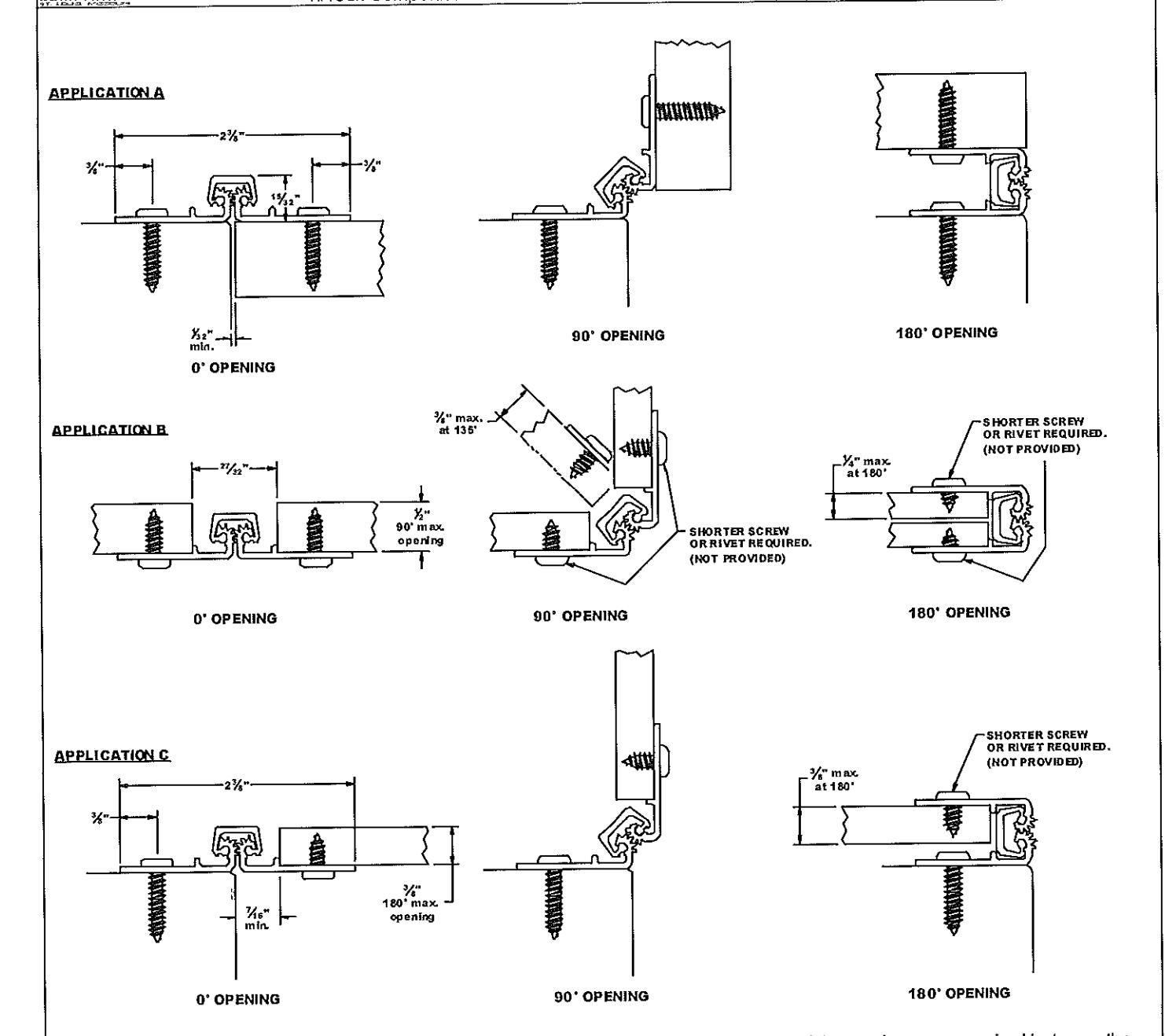
ROTON Model 500-220 is an Aluminum Continuous Geared Full Surface Leaf Hinge. The minimum clearance required between the hinge edge of the door and the frame is different for each application.
For Application A it is 1/32" (0.7mm). Application B it is 27/32" (21.4mm). Application C it is 7/16" (11.1mm).
The maximum door thickness must also be considered for each specific application and door swing (see illustrations above).
Hinge Length
The 500-Series Hinges are supplied in four standard lengths. See chart. If the hinge must be trimmed shorter, determine the desired finished length and mark. Be careful not to cut within 1/2" of a bearing or screw hole. The excess length may be removed all from one end or by cutting equal amounts from both ends.
|
Actual Hinge
Length |
Number of Fasteners
(Door Leaf / Frame Leaf) |
|||
|---|---|---|---|---|
| 24" (610mm) | 6/6 | |||
| 36" (914mm) | 9/9 | |||
| 48" (1219mm) | 12 / 12 | |||
| 72" (1829mm) | 18 / 18 | |||
| DWG # 75005220 A | Revision #: 2 R | Rev. Description: | PLACED IN CAD FORMAT | Drawn By: | DW | Date: 021510 |
|---|

ROTON INSTRUCTION SHEET ROTON MODEL: 500-220
PART NO: 75005220 REVISION: 021510
HAGER Companies - 139 Victor Street - St. Louis, MO 63104 1(800)-325-9995
Installation Procedure
Mounting Surface Preparation
With the hinge open, place the frame leaf against the mounting surface. For application B, make certain that the alignment rib is flush against the face of the mounting surface along its entire length. Center the hinge within the opening. Mark and center punch the screw hole locations. Accurate location is important for proper hinge installation.
For wood and metal, drill pilot holes using a 1/8" (3.2mm) bit. For fiberglass, drill pilot holes using a 9/64" (3.6mm) bit. Do not
attach the hinge at this time.
Door Preparation
With the hinge open, place the door leaf against the face of the door. For application B and C, make certain that the alignment rib is flush against the edge of the door along its entire length. Center the hinge on the door. Mark and center punch the screw hole locations. Accurate location is important for proper hinge installation.
For wood and metal doors, drill pilot holes using a 1/8" (3.2mm) bit. For fiberglass doors, drill pilot holes using a 9/64" (3.6mm) bit.
Attach the hinge to the door using the #8 truss head screws provided.
Hanging the Door
Position the door (with hinge attached) at 90° to the mounting surface. Attach the hinge to the frame using the #8 truss head screws provided.
Make a gentle trial swing. Carefully check the door for proper swing and clearance. 2.
Adjusting the Door
If lateral adjustment is required because of excessive or uneven mounting clearance, adjust by loosening or removing the screws of the frame leaf and shimming where needed.
An effective shimming material is 5/8" strips of cloth duct tape. Apply tape to the mounting surface underneath the
hinge leaf in stepped layers to build up to the desired thickness. In a similar manner, a thin continuous plastic or aluminum strip may be used between the mounting surface and
the hinge leaf to adjust the entire door.
Retighten all screws. Make a gentle trial swing. Carefully check the door for proper swing and clearance.