4902 Series Installation Instructions – I-ED01037-Rev03
Open the original PDF document
View PDF

|
•
• 7' (84") Non-Keyed Removable Mullion Primer Coat USP 7' (84") Keyed Removable Mullion Primer Coat USP • • 8' (96") Non-Keyed Removable Mullion Primer Coat USP 8' (96") Keyed Removable Mullion Primer Coat USP • • 10' (120") Non-Keyed Removable Mullion Primer Coat USP 10' (120") Keyed Removable Mullion Primer Coat USP • • 7' (84") Non-Keyed Removable Mullion Fire Rated Primer Coat USP |
DEVICES COVERED IN THIS DOCUMENT: | ||||||
|---|---|---|---|---|---|---|---|
| 7' (84") Keyed Removable Mullion Fire Rated Primer Coat USP | |||||||
| USP | • | 8' (96") Non-Keyed Removable Mullion Fire Rated Primer Coat | • | 8' (96") Keyed Removable Mullion Fire Rated Primer Coat USP | |||
Rev 3, Rev Date: 07/31/2020 Page 1 of 10

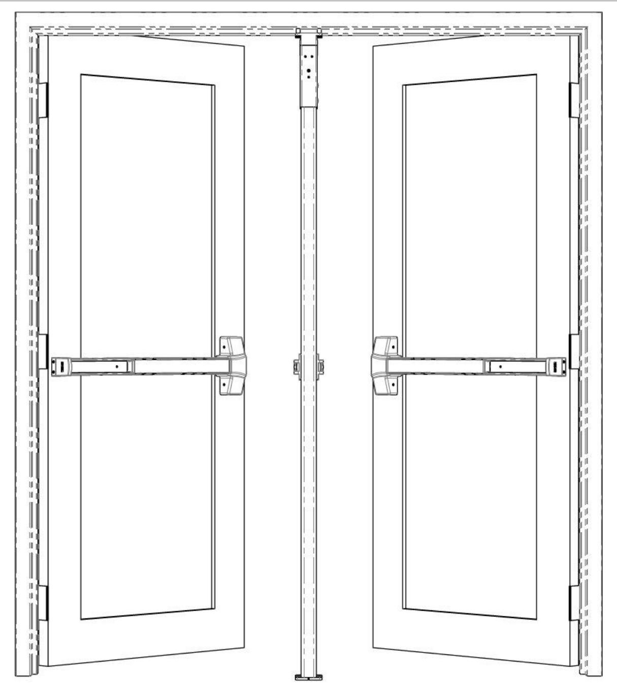
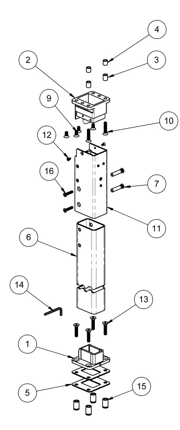
Non-Keyed Removable Mullion (4900U)
|
ITEM
NO. |
QTY. | DESCRIPTION |
|---|---|---|
| 1 | 1 | Mullion Bottom Bracket |
| 2 | 1 | Mullion Top Bracket Assembly |
| 3 | 2 | Top Bracket Shims (5/8in long) for 5/8in stop |
| 4 | 2 | Top Bracket Shims (1/2in long) for 1/2in stop |
| 5 | 2 | Bottom Bracket Shim |
| 6 | 1 | Mullion Post |
| 7 | 2 | Sleeve Nut, 1/4"-20 X 1 5/8" |
| 9 | 4 |
5/16"-18 x 5/8" Flat Phillips Head Cap
Machine Screw |
| 10 | 2 |
5/16"-18 x 1-1/2" Flat Phillips Head
Cap Machine Screw |
| 11 | 1 | Top Fitting of Mullion Tube Assembly |
| 12 | 2 |
#10-24 x 3/8" Flat Phillips Head Cap
Machine Screw |
| 13 | 4 |
5/16"-18 x 1-1/2" Flat Socket Head
Cap Machine Screw |
| 14 | 1 | 3/16" Hex Wrench |
| 15 | 4 | Mullion Bottom Bracket Anchor |
| 16 | 2 |
1/4"-20 x 1-1/4" Flat Phillips Head
Machine Screw |
Rev 3, Rev Date: 07/31/2020 Page 2 of 10

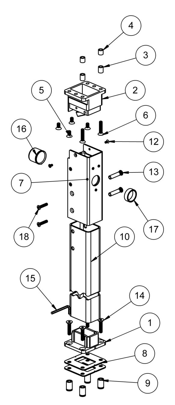
Keyed Removable Mullion (4900X)
| ITEM NO. | QTY. | DESCRIPTION |
|---|---|---|
| 1 | 1 | Mullion Bottom Bracket |
| 2 | 1 | Mullion Top Bracket Assembly |
| 3 | 2 | Top Bracket Shims (5/8in long) for 5/8in stop |
| 4 | 2 | Top Bracket Shims (1/2in long) for 1/2in stop |
| 5 | 4 |
5/16"-18 x 5/8" Flat Phillips Head Cap
Machine Screw |
| 6 | 2 |
5/16"-18 x 1-1/2" Flat Phillips Head Cap
Machine Screw |
| 7 | 1 | Top Fitting of Mullion Tube Assembly |
| 8 | 2 | Bottom Bracket Shim |
| 9 | 4 | Mullion Bottom Bracket Anchor |
| 10 | 1 | Mullion Post |
| 12 | 2 |
#10-24 x 3/8" Flat Phillips Head Cap
Machine Screw |
| 13 | 2 | Sleeve Nut, 1/4"-20 X 1 5/8" |
| 14 | 4 |
5/16"-18 x 1-1/2" Flat Socket Head Cap
Machine Screw |
| 15 | 1 | 3/16" Hex Wrench |
| 16 | 1 | Cylinder Retaining Cup Assembly |
| 17 | 1 | Cylinder Collar - 12mm |
| 18 | 2 |
1/4"-20 x 1-1/4" Flat Phillips Head
Machine Screw |

4900 MULLION SCREW CHART TOP BRACKET INSTALLATION—SEE STEPS 1 THROUGH 3 CONNECT TOP FITTING AND MULLION POST— SEE STEP 4 CONNECT TOP FITTING TO TOP BRACKET—SEE STEP 10 BOTTOM BRACKET INSTALLATION—SEE STEP 8
Rev 3, Rev Date: 07/31/2020 Page 4 of 10

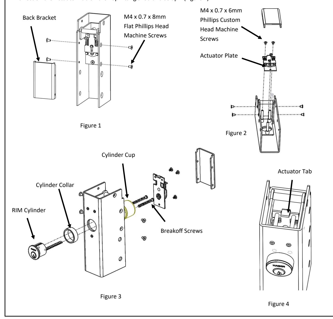
CYLINDER INSTALLATION: KEYED REMOVABLE MULLIONS (4900X) ONLY
- A. Remove the four M4 x 0.7 x 8mm Flat Phillips Head Machine Screws that hold the Back Bracket onto the Top Fitting. Remove the Back Bracket. (Figure 1)
- B. Remove the three M4 x 0.7 x 6mm Phillips Custom Head Machine Screws that hold the Actuator Plate onto the Top Fitting. Note: If replacements screws are needed, M4 x 0.7 x 6mm Pan Phillips Head Screws are an acceptable alternative. (Figure 2)
- C. Slide Cylinder Collar onto RIM Cylinder body. (Figure 3)
- D. Align the Cylinder Tailpiece with the Cylinder Cup Tailpiece Guide Housing. Slide the Cylinder Cup over the RIM Cylinder. Install the Breakoff Screws that came with the RIM Cylinder. Break off the screws to the appropriate length to ensure that the Cylinder Cup tightly holds the RIM Cylinder to the Top Fitting. Be careful not to overtightened the screws to the point that they restrict RIM Cylinder Operation. (Figure 3)
- E. Reinstall the Actuator Plate making sure the RIM Cylinder Tailpiece mates up with the Hub on the Actuator Plate. Reinstall the three M4 x 0.7 x 6mm Phillips Custom Head Machine Screws to secure the actuator plate. (Figure 2)
- F. Reinstall the Back Bracket by reinstalling the four M4 x 0.7 x 8mm Flat Phillips Head Machine Screws. (Figure 1)
- G. Ensure proper operation. Turn the Key in the RIM Cylinder. It should rotate smoothly and when the key is turned in either direction the Actuator Tab on the Top Fitting should raise up. (Figure 4)
Rev 3, Rev Date: 07/31/2020 Page 5 of 10

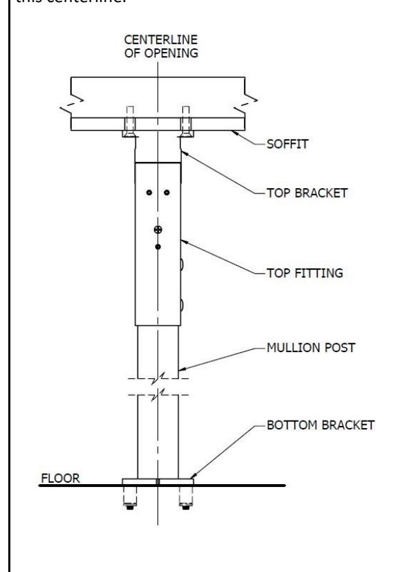
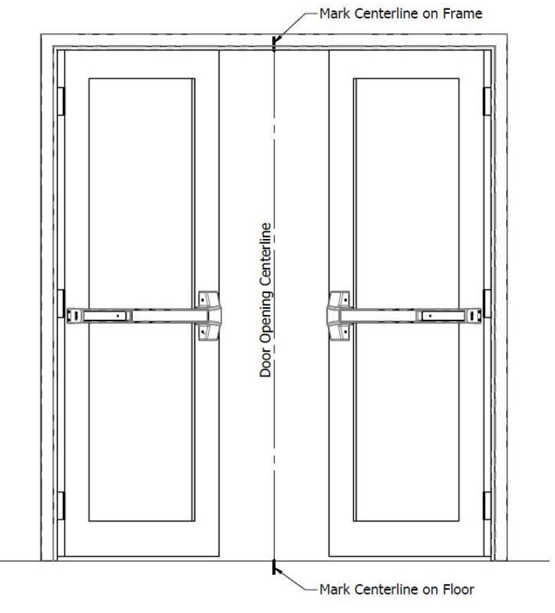
STEP ONE
Measure and mark the center of the width of the door opening at the soffit and at the floor. Be sure the door edges meet at this centerline.
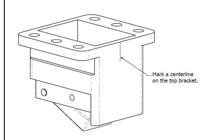
STEP TWO
Measure and mark a centerline on the width of the top bracket.

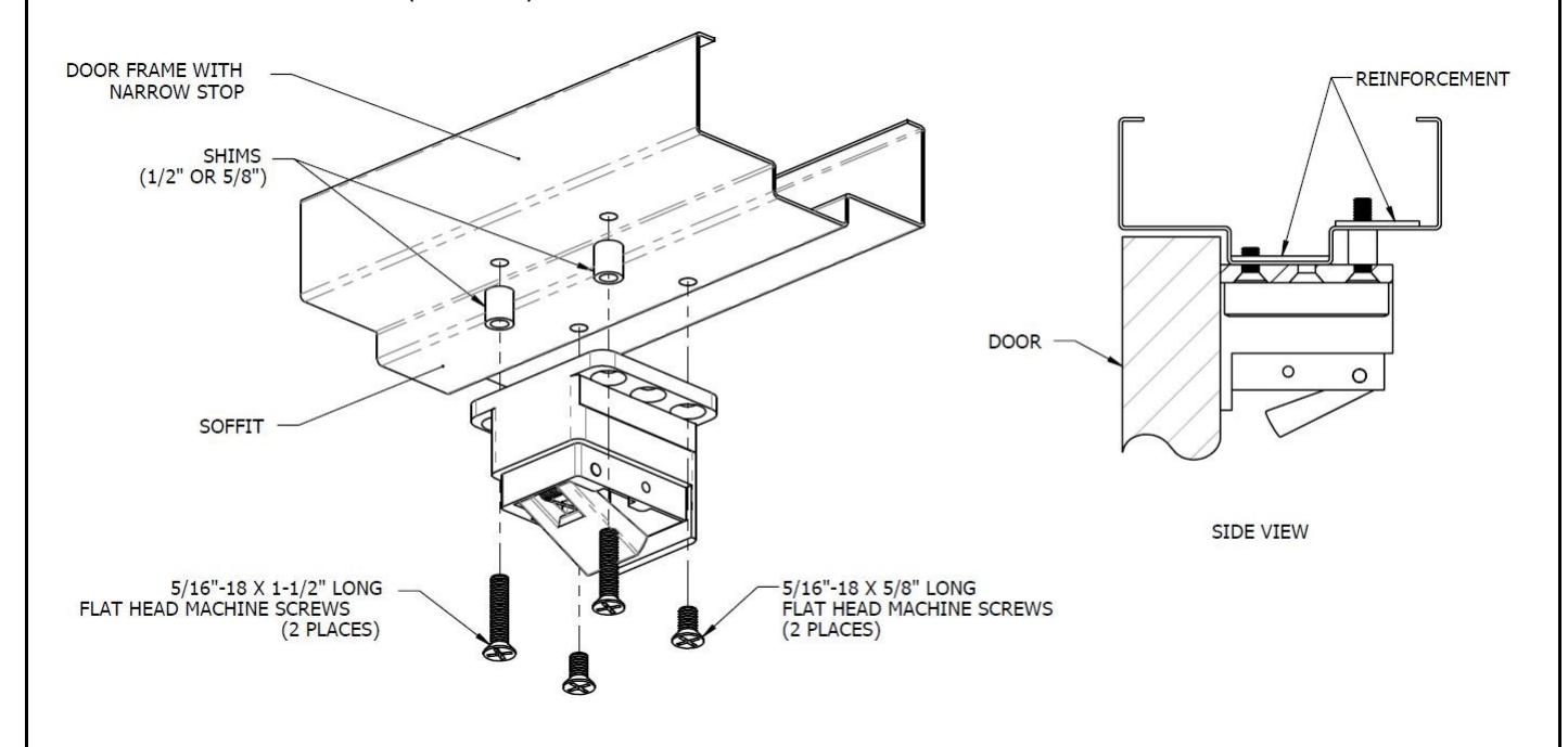
STEP THREE
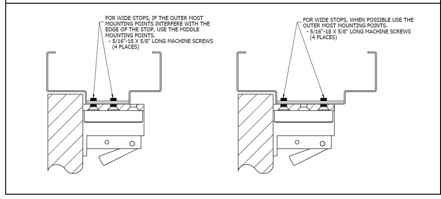
Align, mark hole locations, and install top bracket:
- A. Align the mark from Step 2 with centerline marked in Step 1.
- B. Close the doors and butt the top bracket up to the face of the door.
- C. Mark the four hole locations, dependent on your frame construction (see figures below)
- D. Drill and tap the soffit at the four hole locations for the 5/16"-18 machine screws.
- E. A standard door frame or narrow stop frame will require the use of cylindrical shims, both 1/2" (13mm) and 5/8" (16mm) shims have been included.
- F. Refer to the illustration that matches your application (narrow or wide stop) and install the top bracket using the 5/16"-18 machine screws and shims (if needed).
Rev 3, Rev Date: 07/31/2020 Page 7 of 10

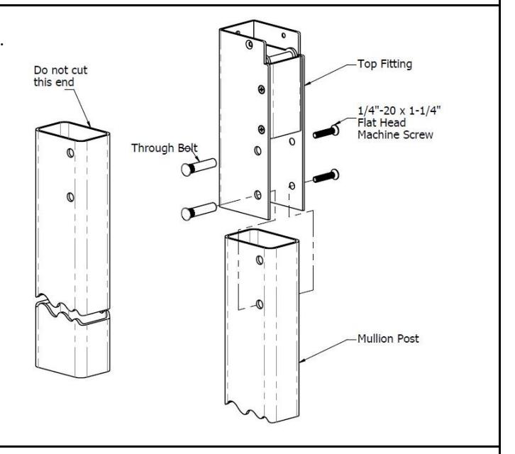
STEP FOUR
Attach mullion top fitting to the mullion post. Secure the two together with the 1/4"-20 machine screws and through bolts (2).
STEP FIVE
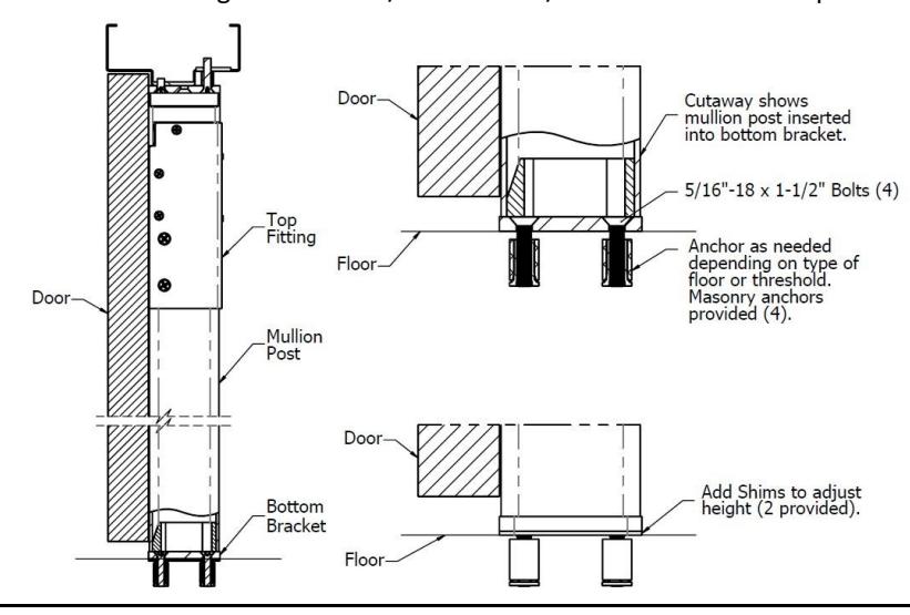
WARNING: If there is a threshold, be sure to cut the threshold so that the mullion bottom bracket can be installed directly on the floor.
STEP SIX
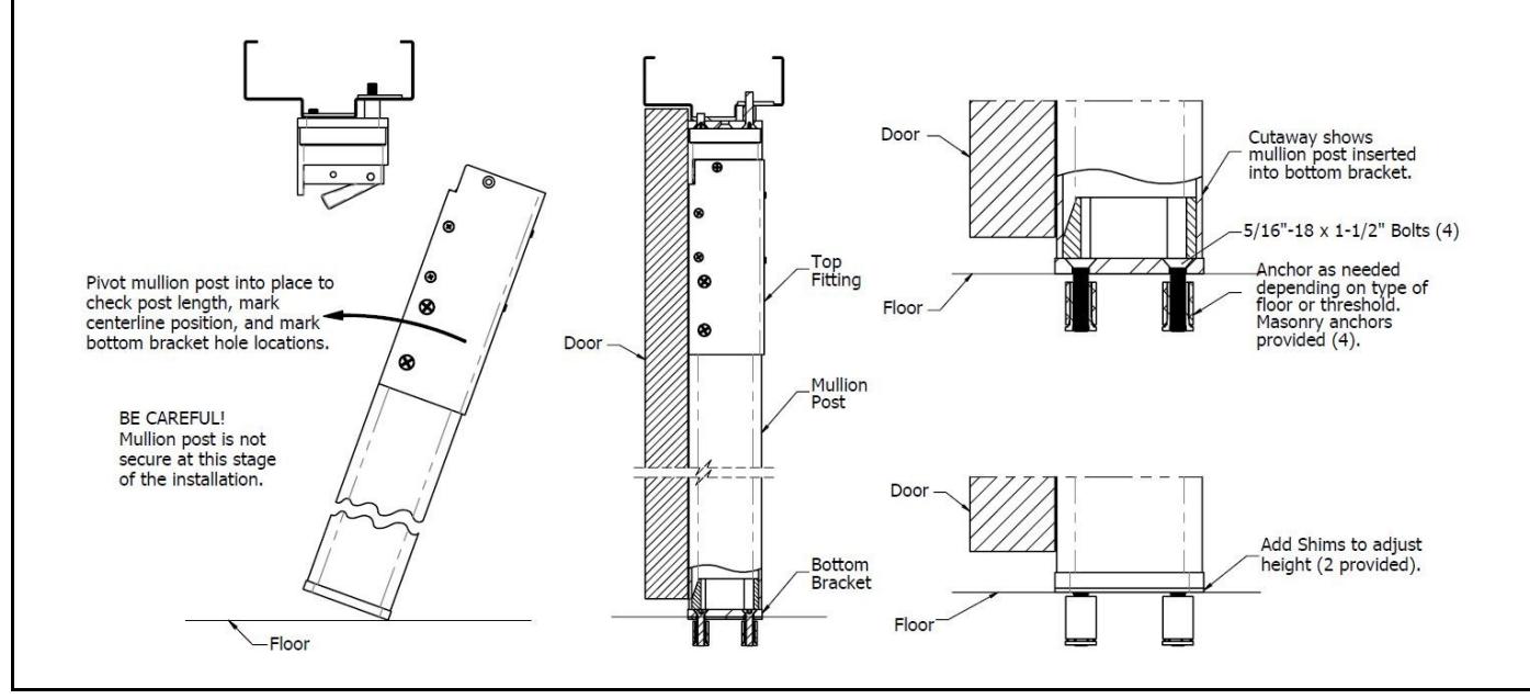
Trial fit the mullion:
- A. Position the bottom bracket on the floor in line with the centerline marked in Step 1.
- B. Insert the mullion post into the bottom bracket and pivot the top end into the top bracket. Close the doors and align the mullion post so it is up against the doors.
- C. Align the notch in the bottom bracket with the centerline marked on the floor in Step 1.
Rev 3, Rev Date: 07/31/2020 Page 8 of 10

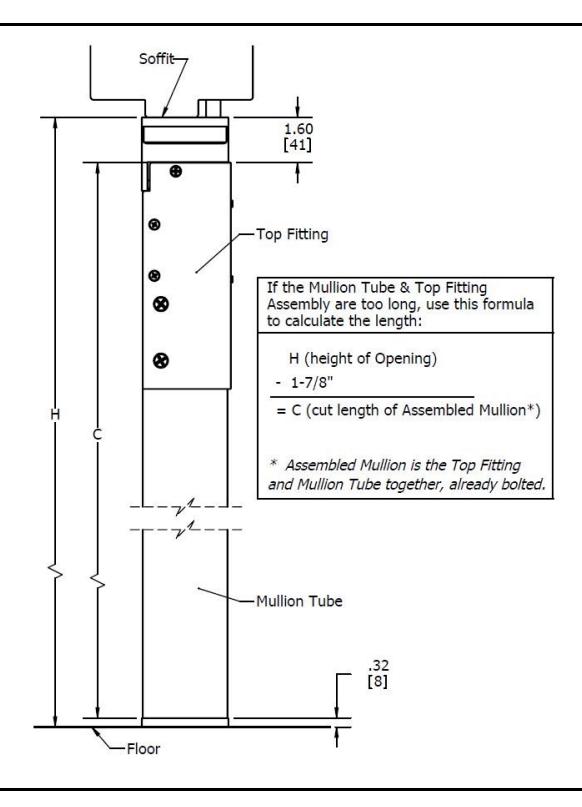
STEP SEVEN
If the mullion post/top fitting assembly fits, skip to the next step. If it is too long and will not fit into the top bracket, use the formula shown to the right to cut the mullion to the proper length. Take the height of the opening, which is from the soffit face to the floor, and subtract 1- 7/8" (48mm). This will be the cut length of the mullion assembly. Be sure to cut from the bottom end of the mullion post. The top end will have the fitting attached from Step 4.
STEP EIGHT
Align, mark hole locations, and install bottom bracket.
- A. If the mullion post was removed, reinstall and align (see step 6).
- B. Once the mullion post and bottom bracket have been properly aligned, mark the four hole locations.
- C. Carefully remove the mullion post and the bottom bracket.
- D. Drill and prepare the mounting holes as needed for the type of floor.
- E. If using the provided machine screw anchors for masonry applications, drill a 5/8" diameter hole by 1-1/8" deep. Use standard practices for installing and securing the anchor.
- F. Secure the bottom bracket to the floor using four of the 5/16"-18 x 1-1/2" flat socket head cap machine screws.
Rev 3, Rev Date: 07/31/2020 Page 9 of 10

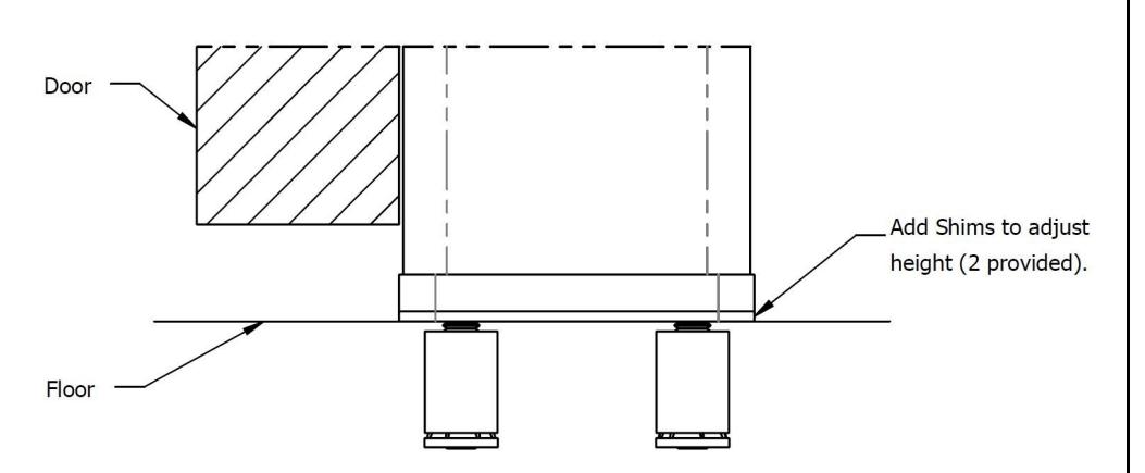
STEP NINE
Replace the mullion post into the bottom bracket and pivot the top upward so it latches in place. The mullion post should snap firmly into the top bracket. If there is too much gap (1/8" or more between mullion post and top bracket), install shims provided to raise the bottom bracket.
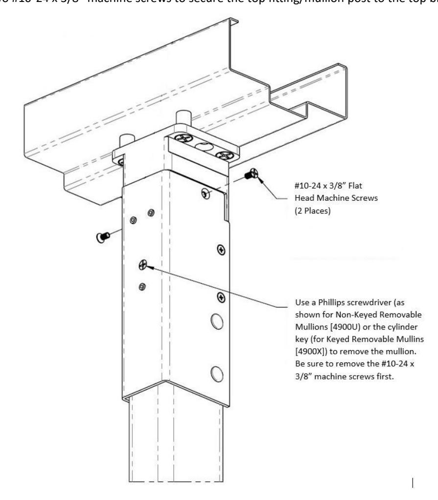
STEP TEN
The Non-Keyed Removable Mullion is removed by inserting a Phillips screwdriver into the crosshair spindle located on the face of the top fitting. The Keyed Removable Mullion is removed by turning the key of the cylinder located on the face of the top fitting. Rotate the spindle or turn the key to ensure the mullion is easily removed. Reinstall the mullion to make sure it smoothly snaps into place. Install the two #10-24 x 3/8" machine screws to secure the top fitting/mullion post to the top bracket.
Rev 3, Rev Date: 07/31/2020 Page 10 of 10