4700 Series Trim Installation Instructions – I-EA00791
Open the original PDF document
View PDF

DEVICES COVERED IN THESE INSTRUCTIONS:
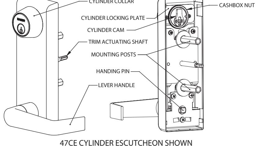
47CE Cylinder Escutcheon - Key Locks & Unlocks Lever 47DT Dummy-Pull When Dogged Night Latch - Key Retracts Latchbolt Blank Escutcheon - Always Operable 47NL 47BE
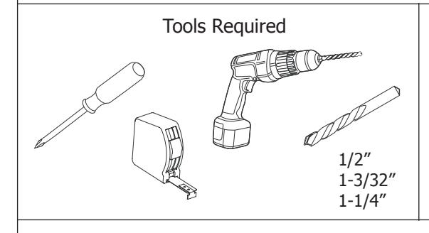
TOOLS

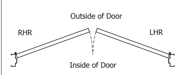
Door Handing
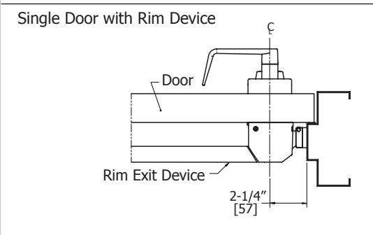
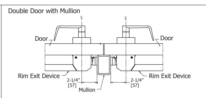
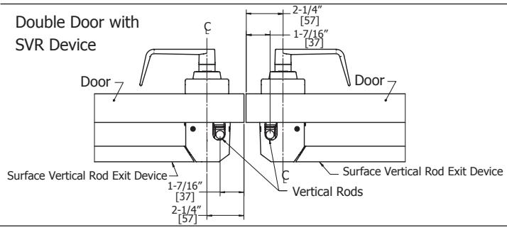
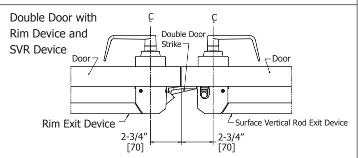
APPLICATIONS
10/28/2011 1 of 3

INSTRUCTIONS
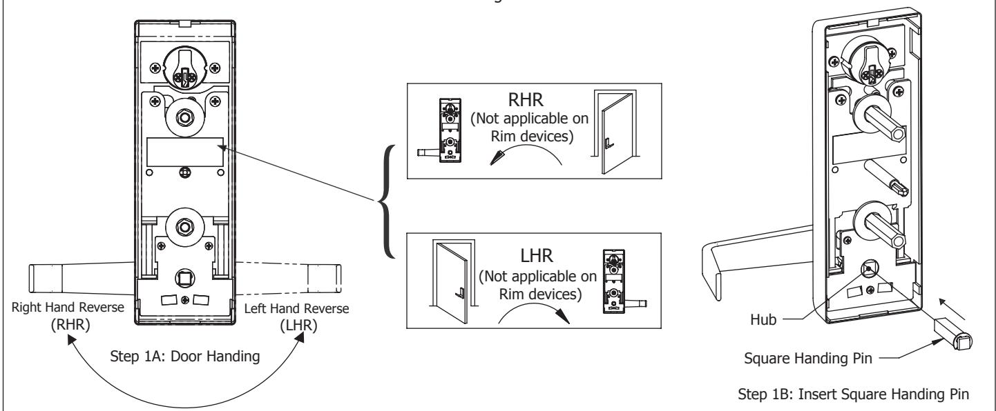
1. Set trim handing.
- A. Rotate lever handle to the right or left direction to match desired door handing.
- B. Insert square handing pin into hub as shown.
- C. For Surface Vertical Rod devices only, be sure the handing matches what is indicated on the product box label. Surface Vertical Rod handing cannot be changed in the field.
Note: See back of trim for a label that indicates which direction to position handle for RHR or LHR handing. The label also indicates which direction the trim actuating shaft should rotate.
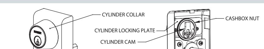
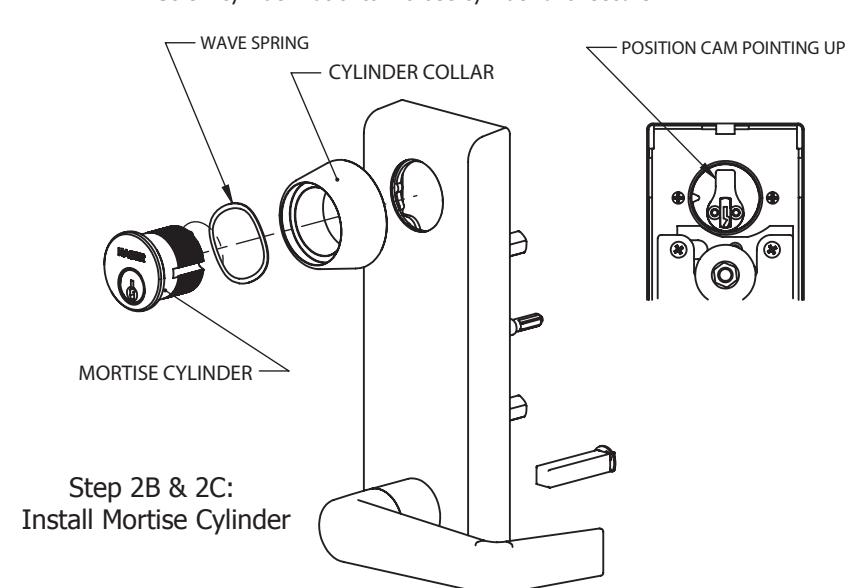
2. Install mortise cylinder.
- A. Remove key from mortise cylinder.
- B. Slide wave washer (if desired) and cylinder collar onto mortise cylinder body.
- C. Install mortise cylinder into escutheon trim with cam position as shown.
- D. Install cylinder locking plate and use stet screws to secure.
- E. Screw cylinder nut onto mortise cylinder until secure.
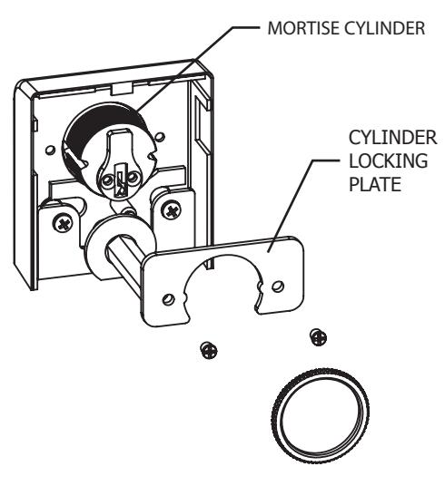
Step 2D + 2E: Install Cylinder Locking Plate
10/28/2011 2 of 3

INSTRUCTIONS (CONTINUED)
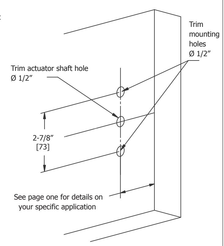
- 3. Mark and drill mounting holes for escutcheon trim.
- A. Mark horizontal centerline by matching it to exit device centerline, which can be found on push side of door.
- B. Apply template to door using centerline. Refer to Applications section on page one to determine location of vertical centerline. Vertical centerline should match exit device vertical centerline located on push side of door.
- C. Mark and drill 1/2" holes for mounting posts as shown on template.
- D. Mark and drill 1/2" hole for trim actuator shaft, which mates with exit device (not required for 47DT). See exit device instructions for further details.
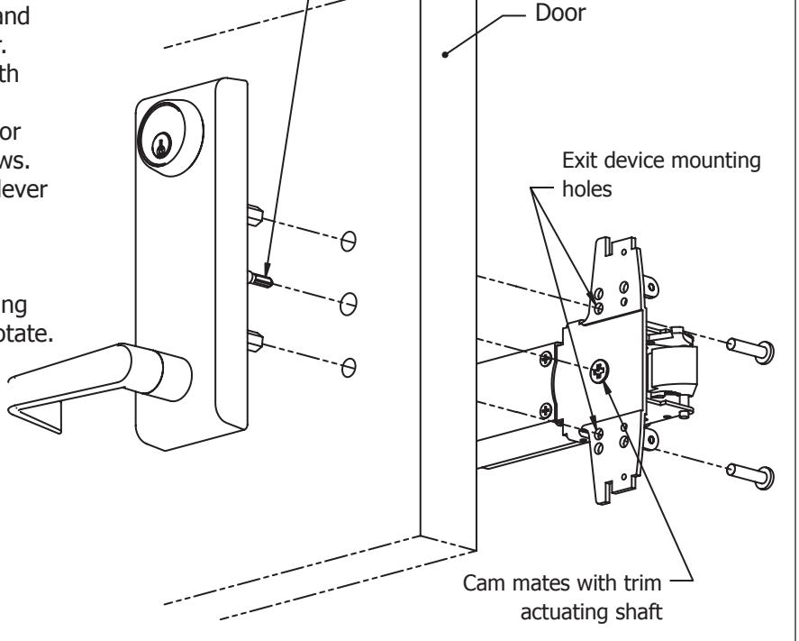
4. Install escutcheon trim.
A. Insert trim mounting posts and actuating shaft through door.
B. Mate trim actuating shaft with cam on back of exit device.
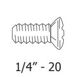
C. Secure from push side of door with provided 1/4" - 20 screws.
D. Test installation by rotating lever handle or key to verify trim activates exit device.
Note: Dummy trim is only for pulling door. The handle does not rotate.
10/28/2011 3 of 3
Trim actuating shaft