4700 Series Installation Instructions I-ED00790-Rev03
Open the original PDF document
View PDF

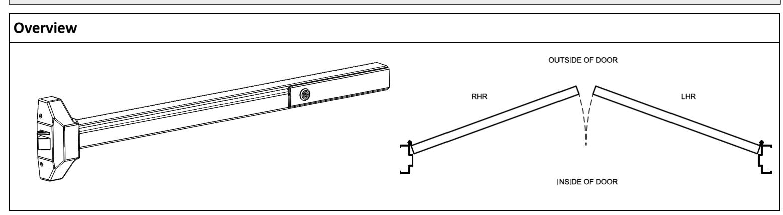
4700 Series Rim Exit Device Installation Instructions Grade 1 I-ED00790
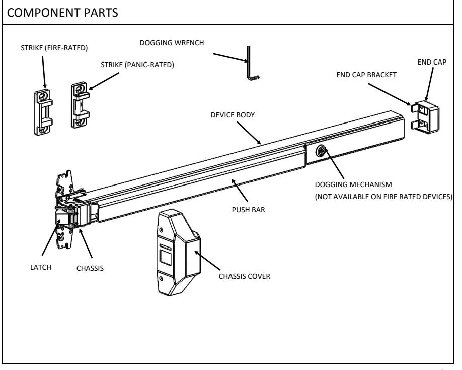
DEVICES COVERED IN THIS DOCUMENT:
4700R Rim Exit Device
4700RF Fire-Rated Rim Exit Device
Page 1 of 3 Rev: 3 Rev Date: 7/16/2018

4700 Series Rim Exit Device Installation Instructions Grade 1 I-ED00790
The exit device is pre-cut for 36" and 48" wide door use. For other door widths, cut exit device to appropriate length. Recommended overall length of the exit device is equal to door width minus four inches. Cut with hacksaw or metal cutting saw blade. Deburr edges.
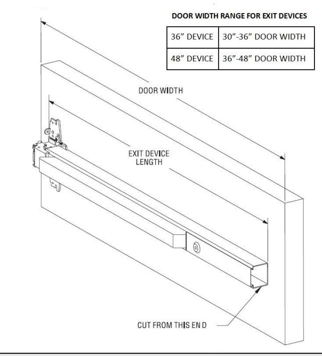
RECOMMENDED OVERALL EXIT DEVICE LENGTH = DOOR WIDTH - 4"
1. CUT EXIT DEVICE TO LENGTH 2. MARK DOOR AND DRILL MOUNTING HOLES
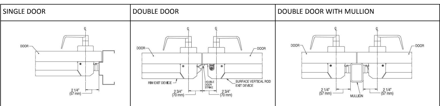
Measure center line of exit device, typically 40" from finished floor. Fold and apply template to door and up against stop. Mark and drill holes as shown on template. Be sure the vertical line of the exit device mounting holes is 2-1/4" from the face of the stop. Do not drill center hole on strike until after strike has been mounted and adjusted.
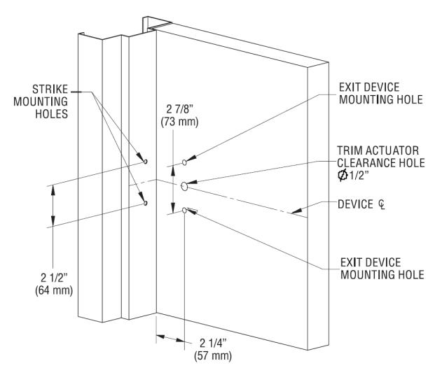
- For metal doors, drill and tap 1/4"-20 machine screws for both exit device and strike.
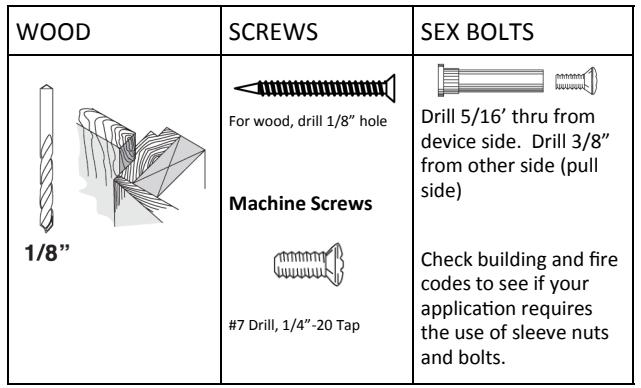
- For wood doors, pre-drill 1/8" holes.
- If mounting trim, drill 5/16" clearance holes on exit device side (push side) of door and 1/2" holes on pull side. Trim requires and additional 1/2" clearance hole for the trim actuating shaft (not required for dummy trim).
- If using sex bolts, drill 5/16" clearance holes on exit device side (push side) of door and 3/8" on pull side.
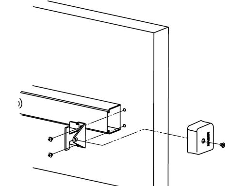
3. INSTALL DEVICE 4. INSTALL END CAP
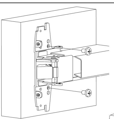
device chassis. Mount exit device using the two the template.
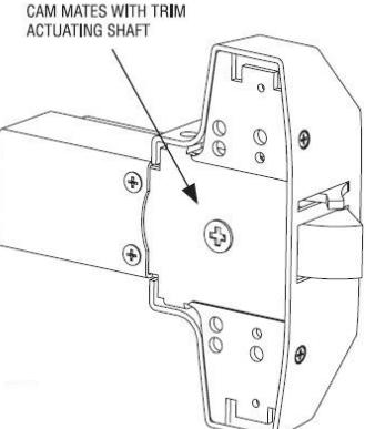
If using trim, be sure to line up trim actuating shaft (tailpiece) with cam located on back of exit device chassis.
Screws
Metal door/sex bolt: 1/4"-20 machine screws (2)
Wood door: #12 wood screws (2)
Remove head cover from exit mounting holes indicated on
Remove end cap from end cap bracket. Mark hole locations by either using template or holding end cap bracket up against door. Be sure exit device is level before inserting end cap bracket lip into end of device body. Mark, drill and tap holes. Install end cap bracket and end cap.
- For metal doors, drill and tap for 1/4"-20 machine screws.
- For wood doors, pre-drill 1/8" holes.
- For sex bolts, drill 5/16" clearance holes on exit device side (push side) and 3/8" on pull side.
Screws
Metal door/sex bolt: 1/4"-20 machine screws (2)
Wood door: #12 wood screws (2)
Rev: 3 Rev Date: 7/16/2018

4700 Series Rim Exit Device Installation Instructions Grade 1 I-ED00790
5. INSTALL STRIKE 6. INSTALL COVER Install strike using only the top and bottom slotted holes and 1/4" -20 machine screws Install head cover on chassis using provided screws. (metal) or pre-drill 1/8" hole for #12 wood screw. Open and close door to verify latch and deadlatch are aligned properly. For tight fit, move strike away from door. For loose fit, move strike towards door. Once strike is adjusted, install center screw. Fire-rated strike does not use center screw. Screws Metal Stop: 1/4"-20 machine screws (3) Wood Stop: #12 wood screws (3) Fire-rated strike
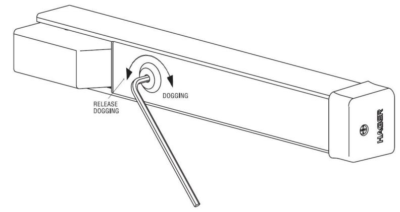
7. DOG DEVICE
For increasing the life of this device, dog device down during high traffic periods of the day. (A dogging device is not available on fire rated models.)
Dogging:
Depress push bar, insert dogging hex wrench and turn clockwise 90 degrees. The push bar will remain depressed and the latch will stay retracted.
Release Dogging:
Hold push bar, insert dogging hex wrench and turn counterclockwise 90 degrees. The push bar will return to the up position and latch will extend to lock door
Page 3 of 3 Rev: 3 Rev Date: 7/16/2018