463-463N REQUEST-TO-EXIT SWITCH INSTALLATION INSTRUCTION
Open the original PDF document
View PDF

INSTALLATION INSTRUCTIONS
463 / 463N REQUEST-TO-EXIT SWITCH
Specifications
Input Voltage Requirements:
• 12-24V AC/DC
Current Draw:
• Idle-30mA, Active-150mA
Output:
- 1 Dry Relay Contact, SPDT
- 1 Amp @ 30VDC (Resistive)
Relay Time:
Adjustable – 1 to 40 seconds or Toggle Mode – ON/OFF
Capacitive Switch Operating Environment:
• -40° F to +160°F (-40° C to +70°C)
Dimensions:
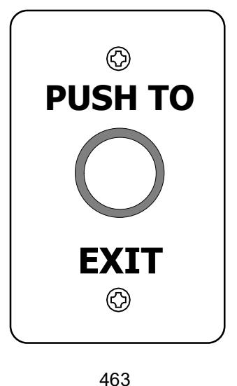
- 463 Standard 4.75" H x 3" W x 1.125" D (120.65 x 76.20 x 28.58 mm)
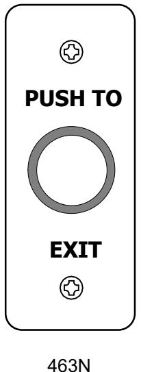
- 463N Narrow 4.75" H x 1.75" W x 1.125" D (120.65 x 44.45 x 28.58 mm)
Mounting Method
463
Mounts directly to a single gang switchbox.
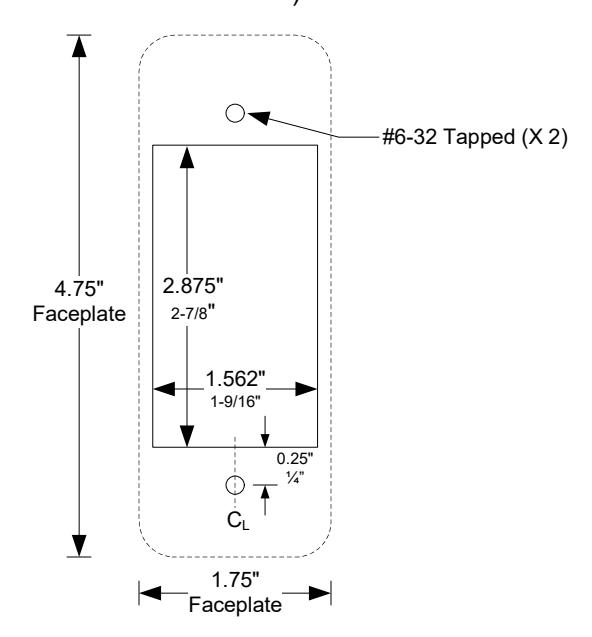
463N: Mullion mount
(See template below. Not to scale.)

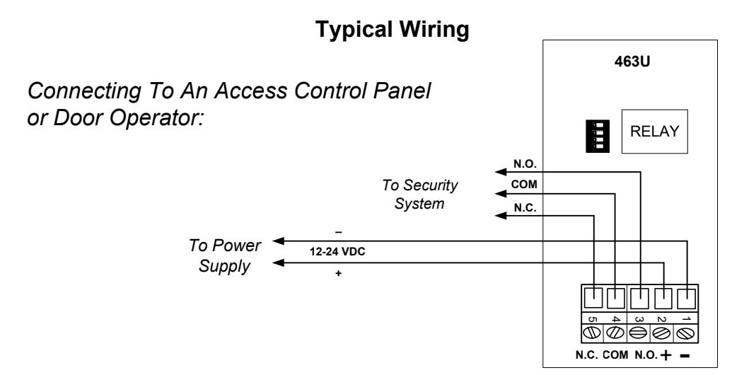
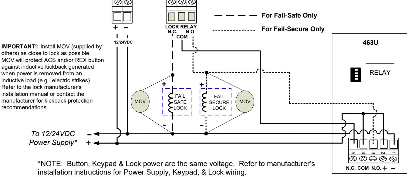
Connecting To an Access Controlled Fail-Safe OR Fail-Secure Locking Device:

Programming
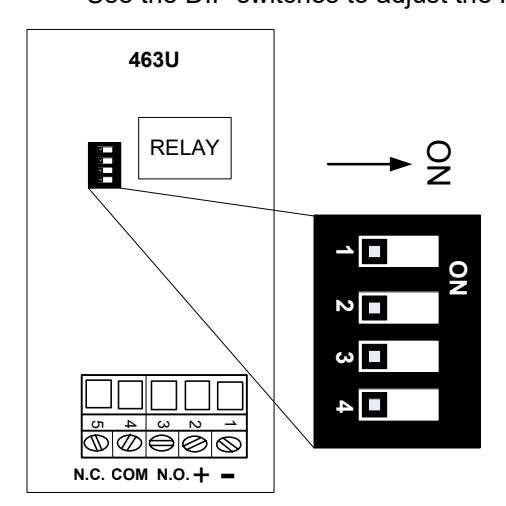
Use the DIP switches to adjust the Relay Activation Time or to reverse the Standby Illumination setting.
| Programming Feature | Dip Switch# | |||
|---|---|---|---|---|
| 1 | 2 | 3 | 4 | |
| 5 second unlock delay | ON | |||
| 10 second unlock delay | ON | |||
| 15 second unlock delay | ON | ON | ||
| 20 second unlock delay | ON | |||
| 30 second unlock delay | ON | ON | ||
| 40 second unlock delay | ON | ON | ||
| Toggle ON/OFF | ON | ON | ON | |
| Standby Illumination | * | |||
Relay Activation Time – Controlled by DIP switches #1, 2 & 3. Minimum Time (DIP switches 1, 2 & 3 are OFF) = 1 second Maximum Time (DIP switches 2 & 3 are ON) = 40 seconds
*Standby Illumination Status – controlled by DIP switch #4. SW #4 OFF = Red (Idle); Flashing Green (Relay Active) SW #4 ON = Green (Idle); Flashing Red (Relay Active)