4601 Series Tim Narrow Stile Trim Installation Instructions – I-ED01164_Rev04
Open the original PDF document
View PDF

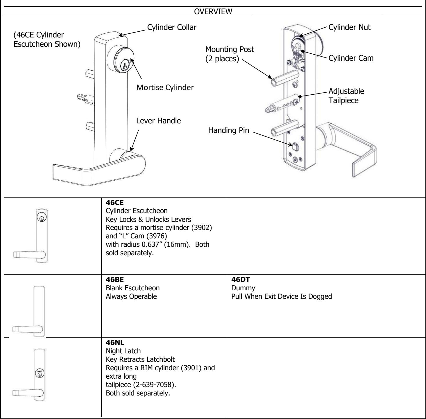
DEVICES COVERED IN THIS DOCUMENT:
- 46CE Cylinder Escutcheon Key locks and unlocks lever
- 46BE Blank Escutcheon Always operable 46NL Night Latch Key retracts latchbolt
- 46DT Dummy Trim Pull when dogged
Rev 4, Rev Date: 6/16/2020 27390048 Page 1 of 6


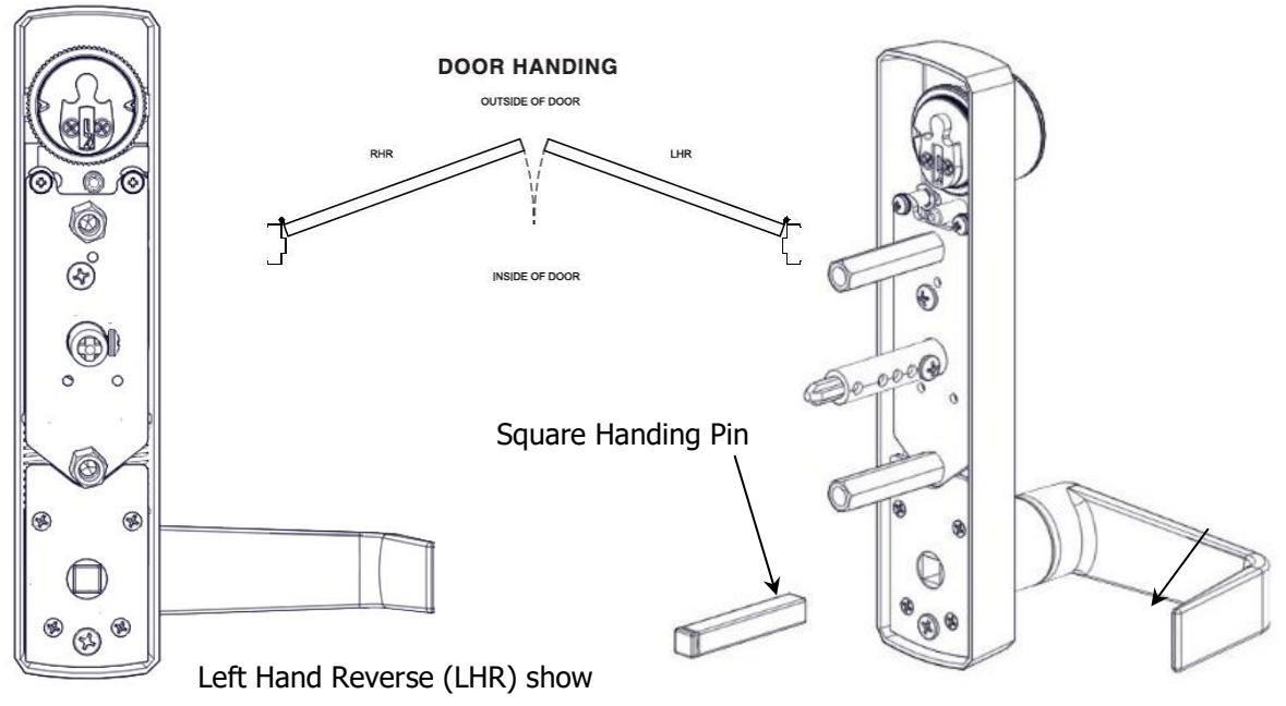
- 1. SET TRIM HANDING
- A. Rotate lever handle to the right or left direction to match the desired door handing.
- B. Align the handle for the desired door handing position and then insert the square handing pin into the trim escutcheon as shown below.
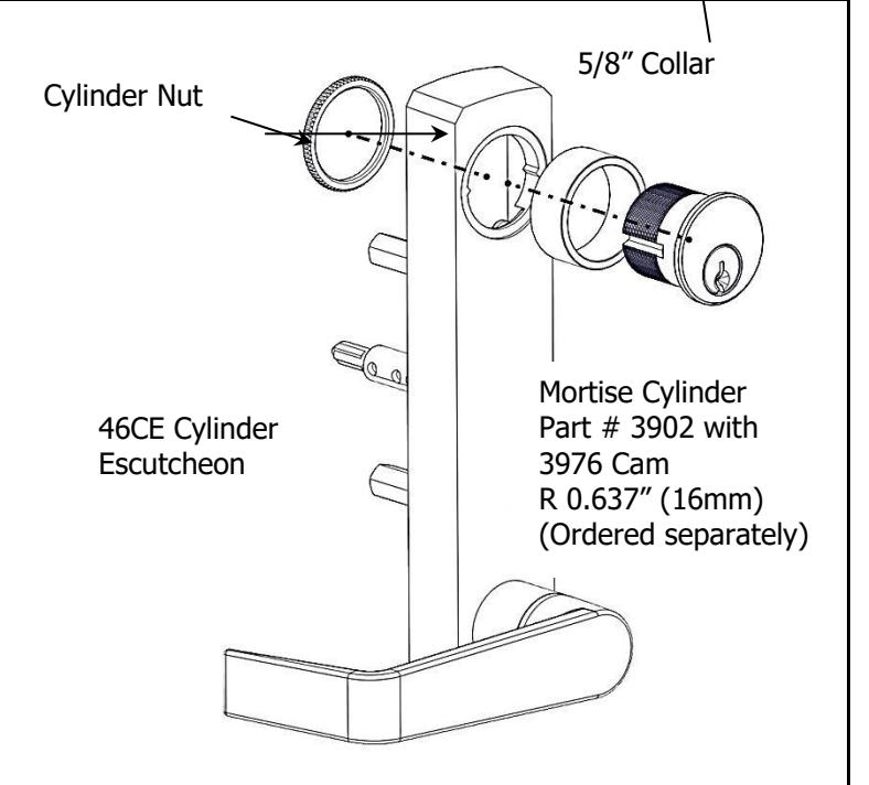
- 2. INSTALL MORTISE CYLINDER (for CE trim only)
- A. Install mortise cylinder into collar and escutcheon trim.
- B. From the back of the trim escutcheon screw cylinder nut onto mortise cylinder until secure.
Test Installation
Insert the key and rotate counterclockwise. Turn the lever handle and observe the tailpiece. It should be unlocked and the tailpiece will rotate. Rotate the key clockwise to lock the trim. Verify that the tailpiece does not rotate when the handle is turned.

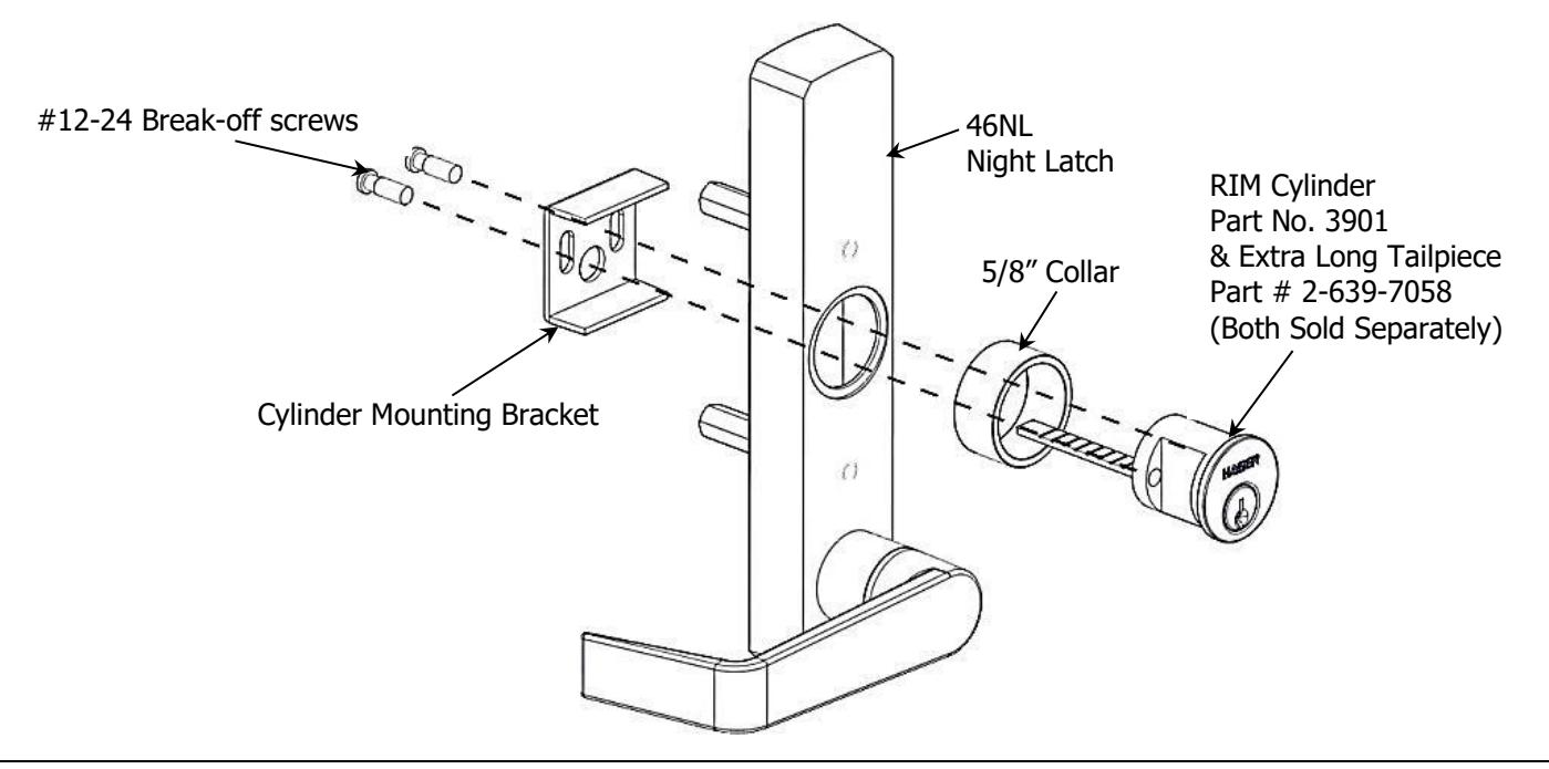
3. INSTALL NIGHT LATCH RIM CYLINDER (for NL trim only)
- A. Replace standard length tailpiece with extra-long tailpiece (2-3/8").
- B. Install rim cylinder into collar and escutcheon trim.
- C. Install cylinder mounting bracket from back side of escutcheon trim as shown below.
- D. Adjust break-off screws to eliminate excess length and secure rim cylinder.
- E. Insert key and rotate. Observe the back of the trim and verify that the tailpiece rotates.
4. DRILL MOUNTING HOLES FOR ESCUTCHEON TRIM
- A. Mark horizontal centerline by matching it to exit device centerline, which can be found on the push side of the door.
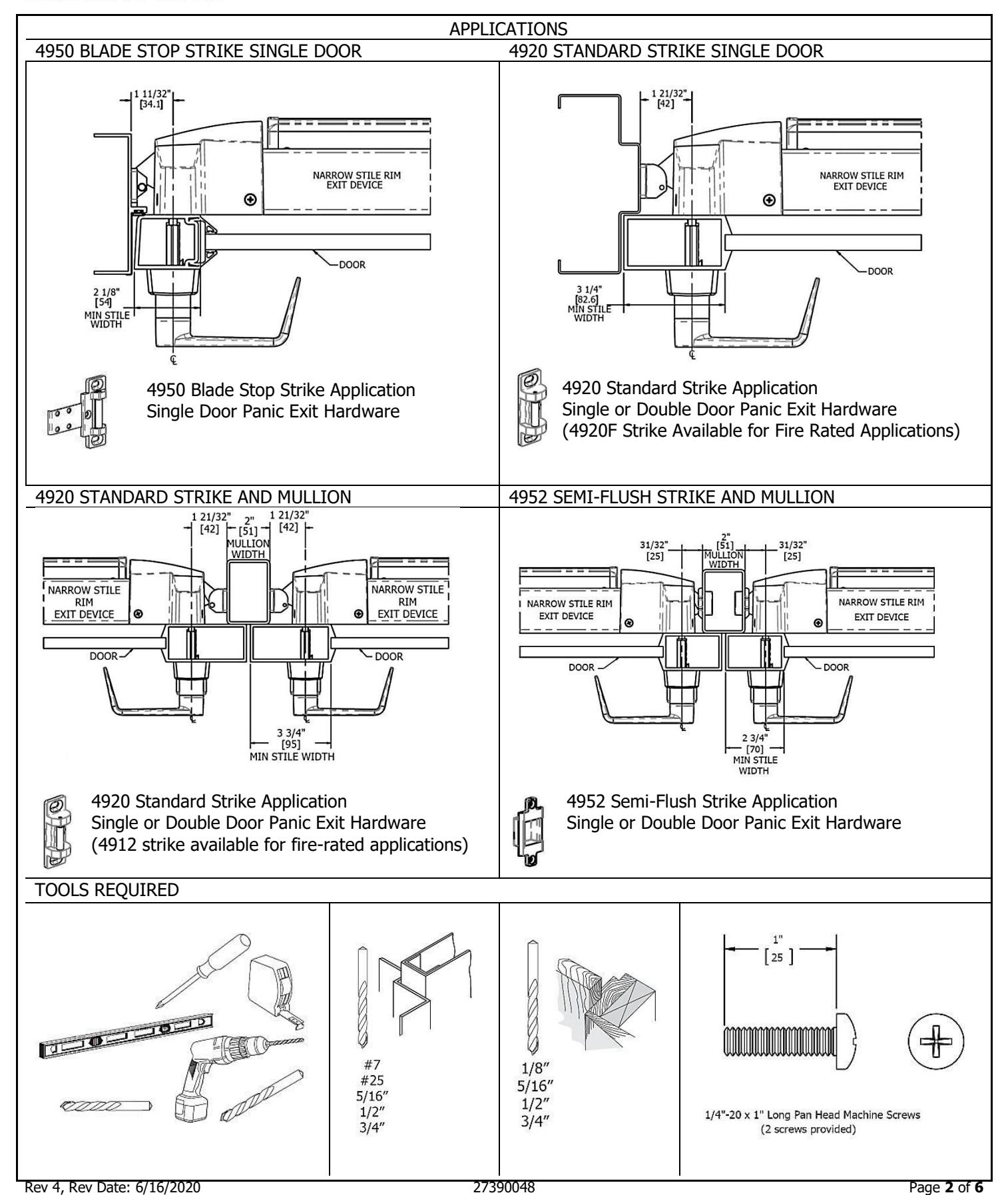
- B. Mark vertical centerline by matching it to exit device centerline, which can be found on the push side of the door. Refer to Applications section on page 2 to determine the location of the vertical centerline.
- C. Apply template to door using centerlines.
-
D. Mark and drill holes as shown below.
- i. Note that the mounting holes are the same for all functions but the tailpiece clearance hole is different depending on function.
Note: Available templates include T-ED01194 – 4600 Trim Template (BE, CE,DT) and T-ED01195 – 46NL Trim Template
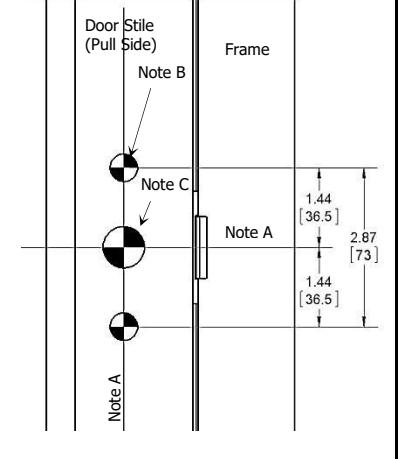
Notes:
-
A. Trim centerline corresponds to exit device centerline.
-
B. Trim mounting clearance holes (2 places):
- i. Drill ø 1/2" [13] holes on pull side. ii. Drill ø 5/16" [8] holes on push side.
-
B. Trim mounting clearance holes (2 places):
-
C. Trim tailpiece clearance hole:
-
i. For CE, NK and BE functions:
- 1. Drill ø 3/4" [19] hole on pull side. 2. Drill ø 1/2" [13] hole on pull side.
- ii. For NL function, drill ø 1/2" [13] thru hole.
- iii. Not required for DT function.
-
i. For CE, NK and BE functions:

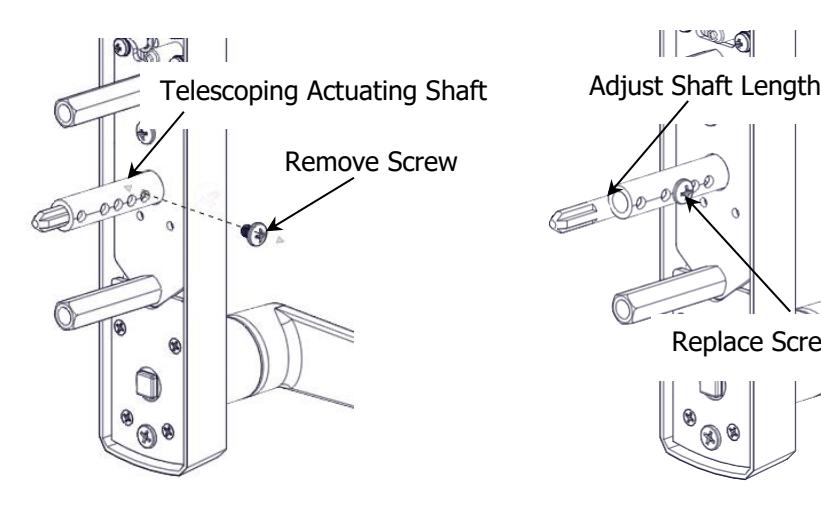
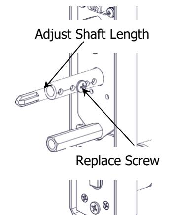
5. ADJUST TELESCOPING ACTUATING SHAFT (for BE and CE trim only)
-
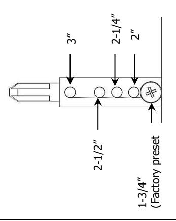
A. The telescoping actuating shaft is preset at the factory for a 1-3/4" thick door. For thicker door applications follow these steps:
- i. Remove the small screw on the side of the actuating shaft and keep it handy for the next step.
- ii. Use the chart below to choose the appropriate setting for your door application. For other door/shim kit thicknesses, use the closest larger size.
- iii. Slide the center shaft out until it lines up properly with the setting you chose in the last step.
- iv. Replace the screw and secure.
- v. Check for proper engagement with the exit device in the next step.
Preset Door Thickness Positions For Telescoping Actuating Shaft
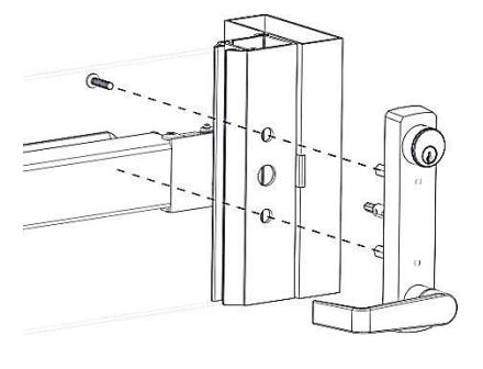
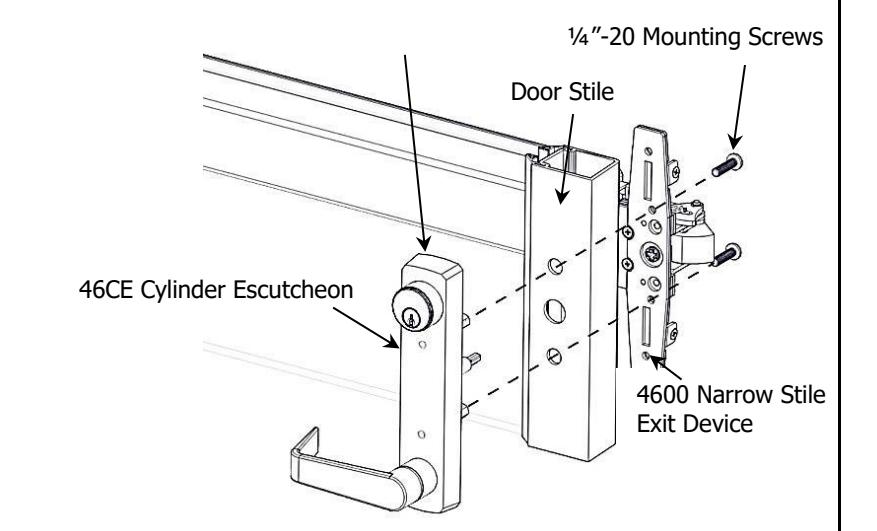
INSTALL ESCUTCHEON TRIM
- A. Insert trim mounting posts and actuating shaft through door.
- B. Mate trim actuating shaft with cam on back of exit device.
- C. Secure from push side of door with provided ¼"-20 machine screws.
- D. Test installation by rotating lever handle or key to verify trim functions properly.


| BLANK | ||
|---|---|---|
Rev 4, Rev Date: 6/16/2020 27390048 Page 6 of 6