4600 Series Installation Instructions i-ed01162_rev2
Open the original PDF document
View PDF

DEVICES COVERED IN THIS DOCUMENT:
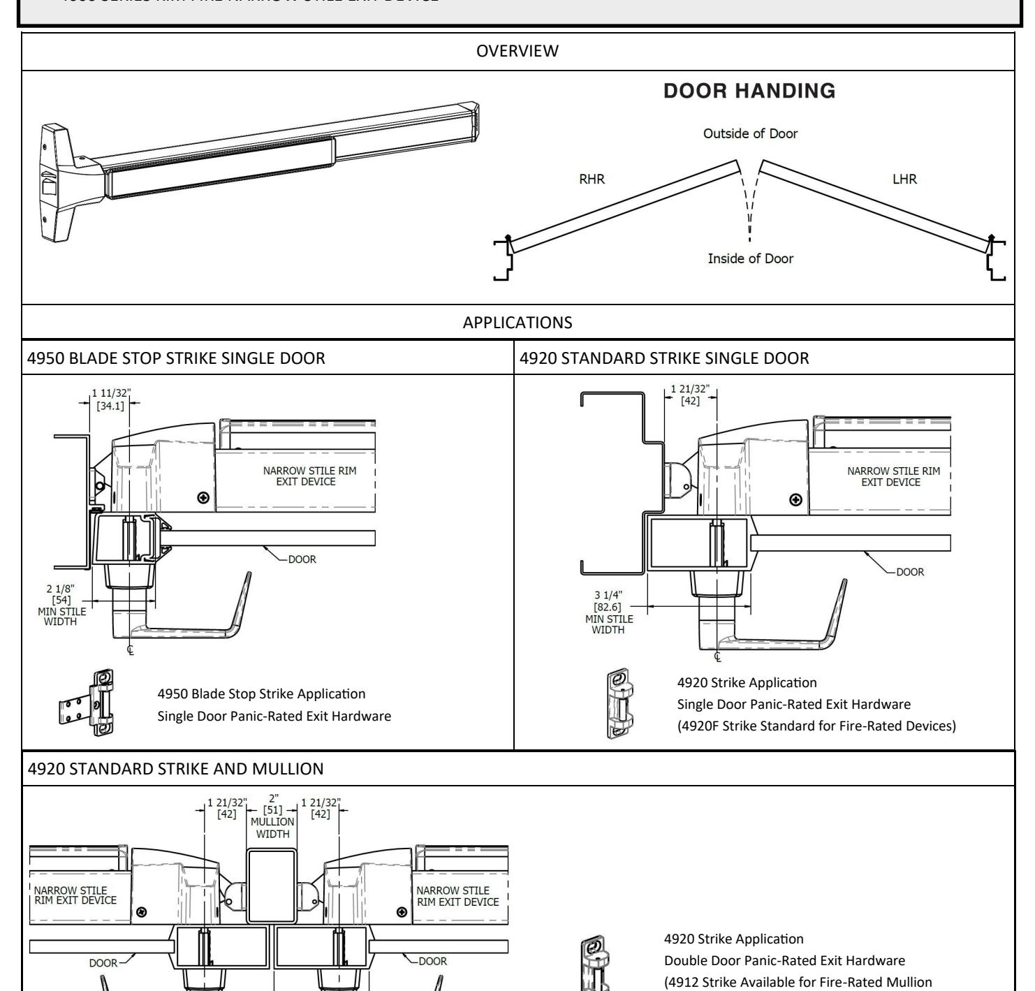
- 4600 SERIES RIM PANIC NARROW STILE EXIT DEVICE
- 4600 SERIES RIM FIRE NARROW STILE EXIT DEVICE
Rev 2, Rev Date: 02/06/2020 Page 1 of 8
Applications)

Page 2 of 8 Rev 2, Rev Date: 02/06/2020

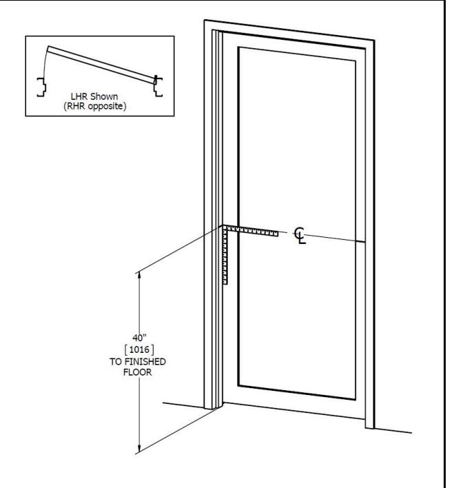
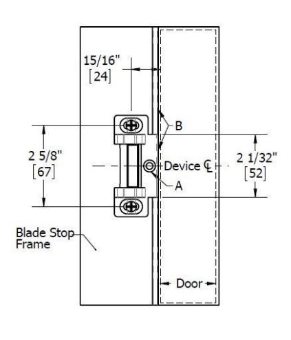
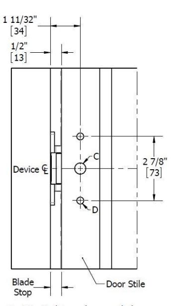
1. MARK DOOR
- A. Measure and draw center line on door and frame, typically 40" from finished floor.
- B. Fold and apply templates to door and frame.
- C. Refer to website for templates.
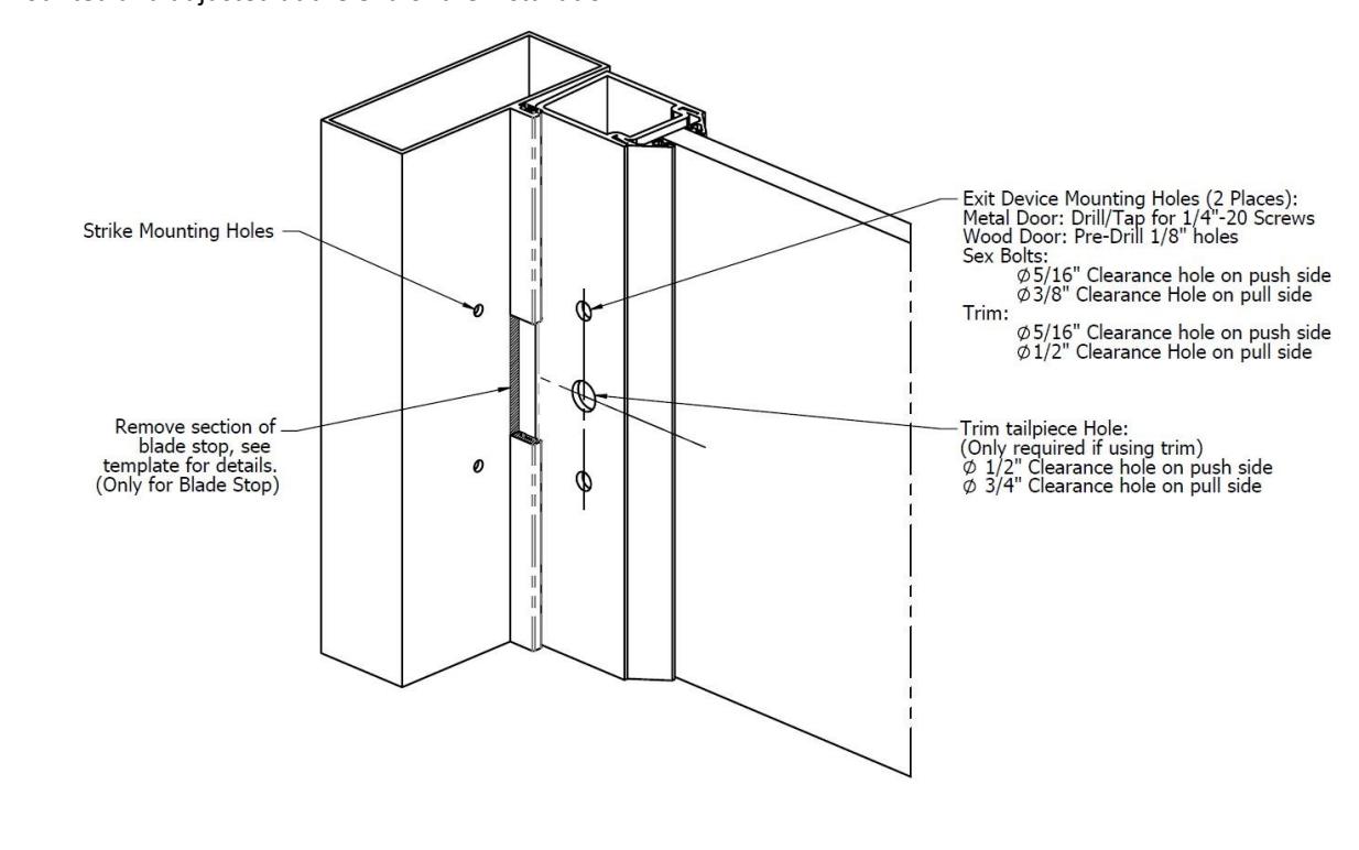
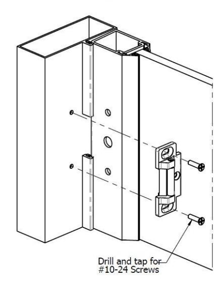
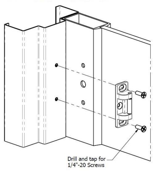
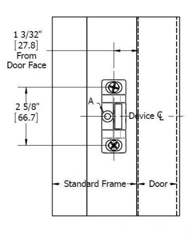
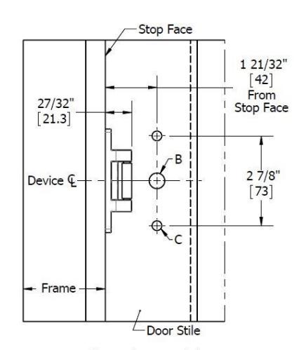
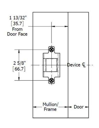
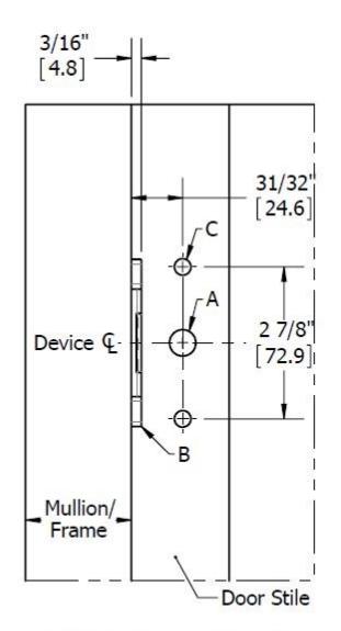
2. DRILL MOUNTING HOLES
A. Mark, drill and tap holes as shown on door and frame templates. Do not drill center hole on strike u ntil after strike has been mounted and adjusted at the end of the installation.
Rev 2, Rev Date: 02/06/2020 Page 3 of 8

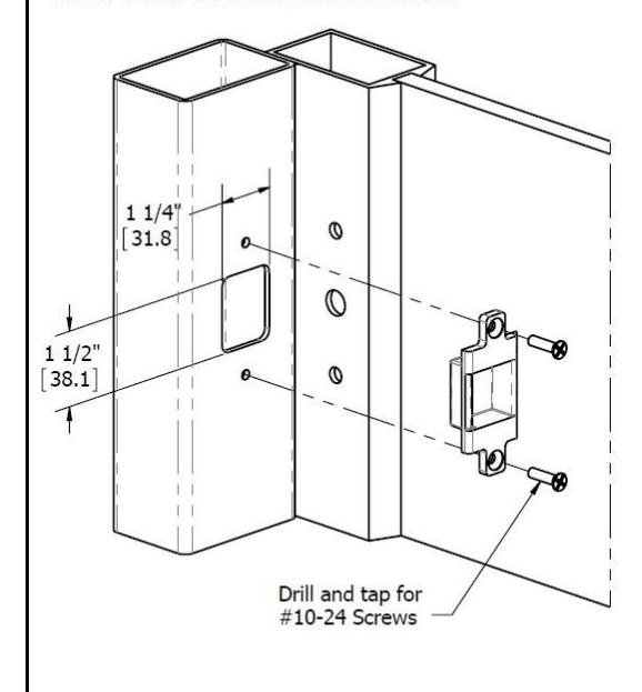
3. INSTALL STRIKE
A. Install strike using the two outer mounting holes.

3. INSTALL STRIKE (CONTINUED)
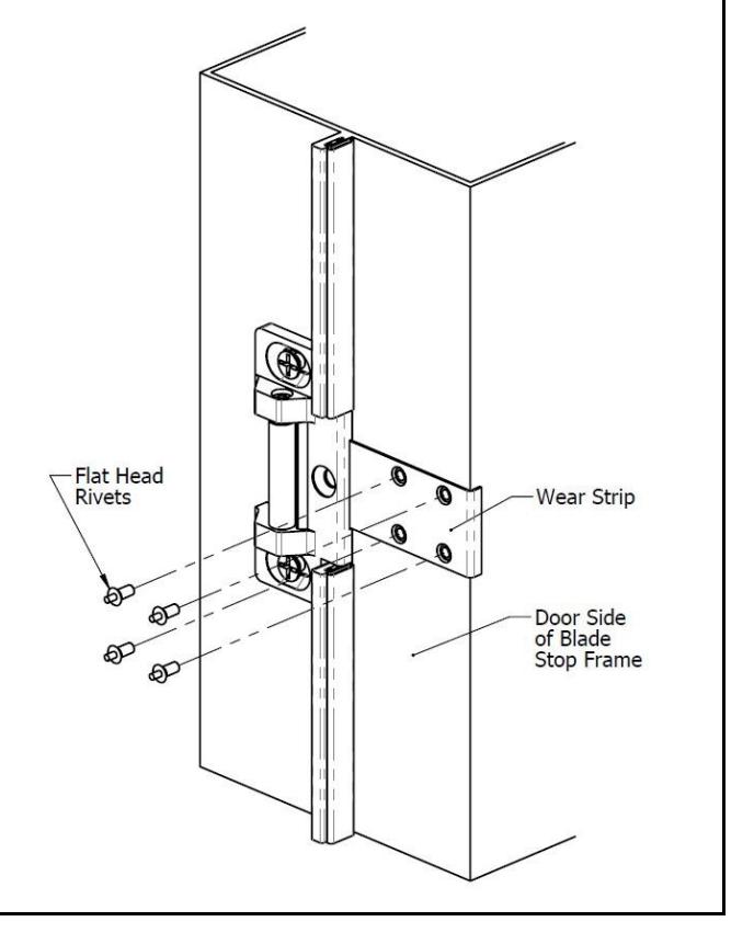
4. INSTALL 4950 WEAR STRIP (SKIP IF USING A DIFFERENT STRIKE)
- A. Place wear strip on frame and center on strike.
- B. Hold in place and mark all 4 hole locations.
- C. Drill 1/8" diameter holes in 4 places and install wear strip with Flat head drive rivets (provided).
Rev 2, Rev Date: 02/06/2020 Page 5 of 8
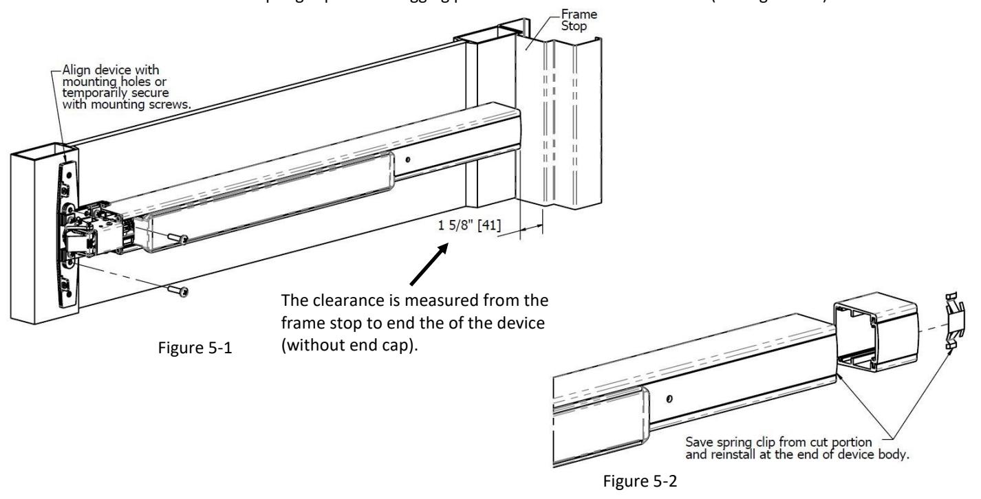
5. CUT EXIT DEVICE TO LENGTH
- A. Remove head cover from exit device chassis.
- B. Align device with mounting holes and measure to determine length to cut device. The clearance between the frame stop and end of exit device (with end cap removed) is 1-5/8" (See Figure 5-1).
- C. Cut device square with hack saw or metal cutting saw blade and deburr edges. Make sure cut is straight or the end cap won't sit flush. Be sure to save the spring clip on the dogging plate cover for use on the device. (See Figure 5-2).
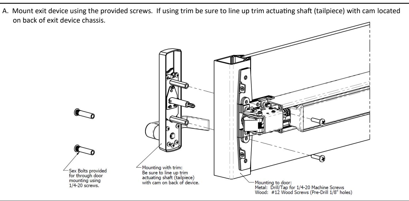
6. INSTALL DEVICE
Page 6 of 8 Rev 2, Rev Date: 02/06/2020
7. INSTALL FLUSH END CAP
- A. Remove the flush end cap from the flush end cap bracket.
- B. Mark hole locations by holding flush end cap bracket up against door and device. Be sure exit device is level before inserting the flush end cap bracket into the device.
- C. Mark and drill/tap holes.
- D. Install flush end cap bracket and flush end cap using supplied screws (See Figure 7-1). If the flush end cap is not flush with the exit device, remove flush end cap and adjust the mounting screws and the flush end cap bracket as needed (See Figure 7-2)..
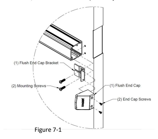
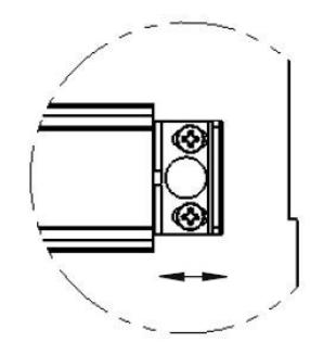
Figure 7-2
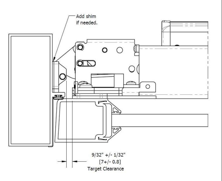
8. TEST AND ADJUST
- A. Check engagement between exit device and strike. Shim strike as needed for a 9/32" clearance between strike and chassis.
- B. Check opening and closing door. Repeat this with head cover to make sure head cover does not hit the strike.
- C. If device operates properly, drill/tap and install center screw in strike (if applicable).
Rev 2, Rev Date: 02/06/2020 Page 7 of 8

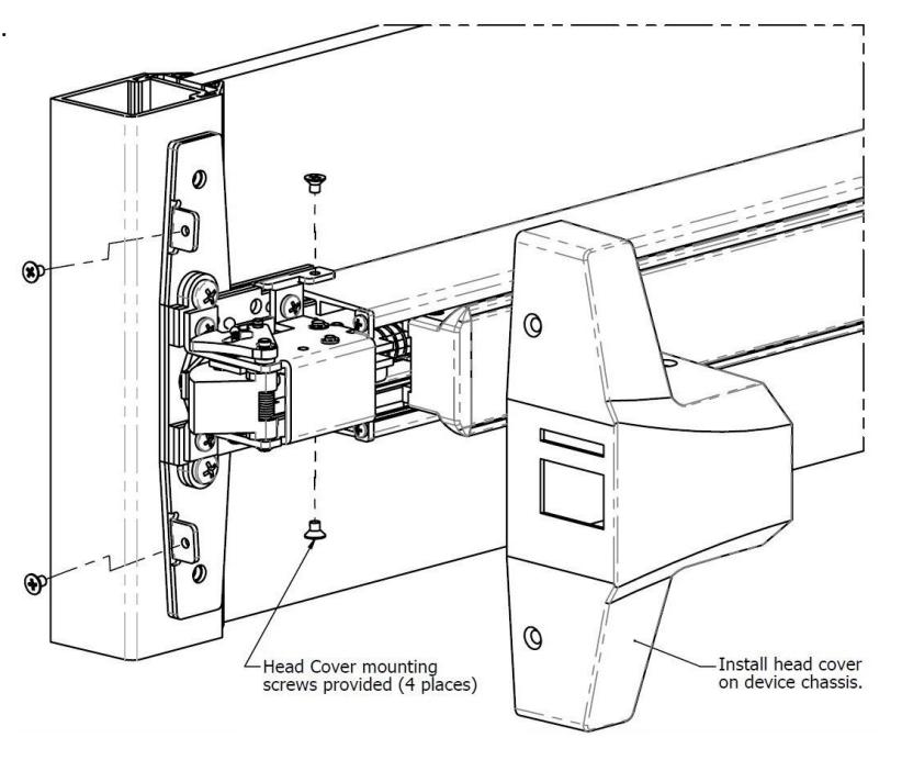
9. INSTALL HEAD COVER
A. Install head cover on chassis using provided screws.
10. DOGGING DEVICE
A. For increased life of the device, dog the push bar down during high traffic periods of the day.
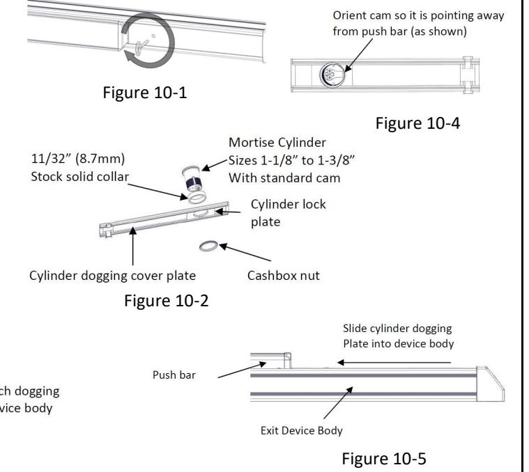
B. Hex Wrench Dogging:
To dog the device, press the push bar, insert the hex dogging wrench and turn clockwise 35 degrees. The push bar will remain depressed and the latch will stay in the Door Open Position. (See Figure 10-1) To release the dogging, hold the push bar down, insert the hex dogging wrench and turn counter-clockwise 35 degrees. The push bar will return to the up position and the latch will actuate to lock the door.
C. Cylinder Dogging:
Required hardware for cylinder dogging includes one (1) mortise cylinder, lengths 1-1/8", 1-1/4" or 1-3/8"with a standard cam (0.723" [18mm] screw center to tip of cam): and one (1) Hager Cylinder Dogging kit (4925R) which includes one (1) 11/32" [8.7mm] solid cylinder collar and cashbox nut. (See Figure 10-2) Remove and discard the hex wrench extension. (See Figure 10-3) The cylinder should be oriented so the cam is pointing away from the exit device push bar. (See Figure 10-4) Install the dogging cover plate with the cylinder and test the dogging. (See Figure 10-5) Depress the push bar, insert the key and turn the key clockwise to dog the device. Turn the key counter-clockwise to release the dogging.
Figure 10-3
Page 8 of 8 Rev 2, Rev Date: 02/06/2020