4600 Series CVR Installation Instructions for Aluminum Doors – I-ED01933-Rev03
Open the original PDF document
View PDF

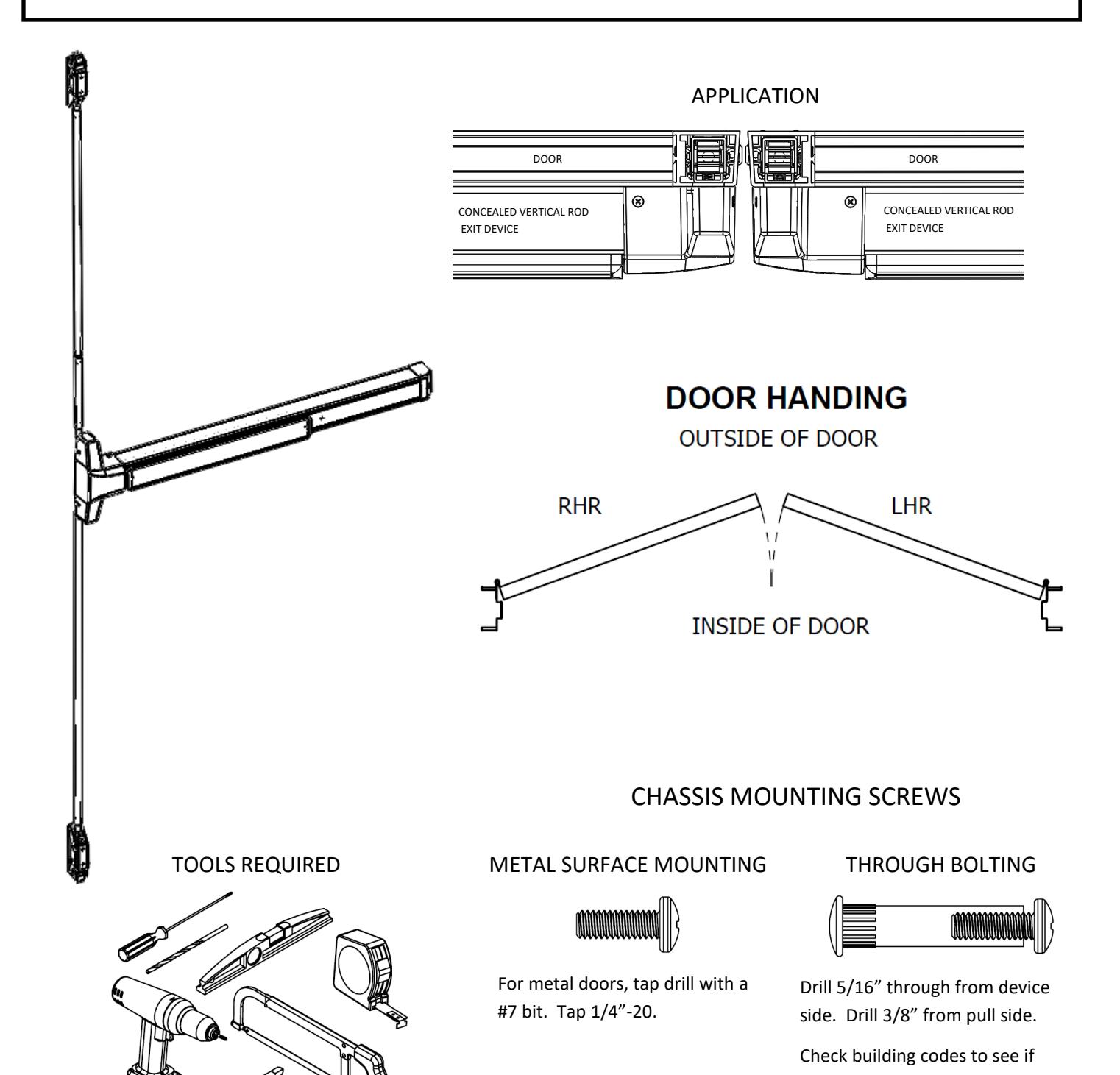
DEVICES COVERED IN THIS DOCUMENT:
4600C—NARROW STILE CONCEALED VERTICAL ROD EXIT DEVICE (CVR)
4600K—NARROW STILE CONCEALED VERTICAL ROD LESS BOTTOM ROD EXIT DEVICE (CLB)
Rev 3, Rev Date: 2/13/20 Page 1 of 10
your application requires the use
of sleeve nuts and bolts.

Accessory Packs Included With Device
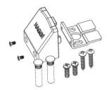
Flush End Cap Pack (available as a replacement part)
| Description | Quantity | Where Used |
|---|---|---|
| Flush End Cap Bracket | 1 | Holds back of device to door |
| Flush End Cap (finished same as device) | 1 | Flush End Cap |
|
End Cap Screws, M4 x 0.7 x 6mm Flathead Undercut
Screws (finished same as device) |
2 | Holds Flush End Cap to Flush End Cap Bracket |
| Sleeve Nut - 1/4"-20 x 1-5/8" (finished same as device) | 2 | Holds Flush End Cap Bracket when Thru bolting |
| Machine Screw, 1/4"-20 x 3/4" - 2B Phillips Pan Head | 2 |
Holds Flush End Cap Bracket when surface mounting
to metal doors or thru bolting all doors |
| Wood Screw, #12 x 1.25" Phillips Pan Head | 2 | Holds Flush End Cap Bracket when surface mounting |
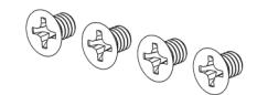
4600 CVR Latch Screw Pack (available as a replacement part) Contains 4 of the screws used to hold the top and bottom latches to the door. They are 1/4"-20 x 3/8" Phillips Flat Head Machine Screws that are finished same as device.
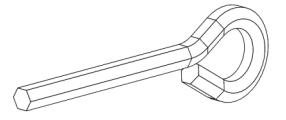
Hex Key for Dogging Pack (available as a replacement part in pack of 10) Contains 1 hex key for dogging the device.
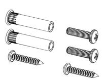
Chassis Screw Pack (available as a replacement part)
| Description | Quantity | Where Used |
|---|---|---|
| Machine Screw, 1/4"-20 x 1" - 2B Phillips Pan Head | 2 |
Holds chassis to door when surface mounting to metal
doors or thru bolting all doors |
| Sleeve Nut - 1/4"-20 x 1-5/8" (finished same as device) | 2 | Holds chassis to door when Thru bolting |
| Wood Screw, #12 x 1.25" Phillips Pan Head | 2 | Holds chassis to door when surface mounting |

Accessory Packs Included With Device In Latch Box
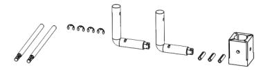
4600 CVR Rod Connector Pack (available as a replacement part)
| Description | Quantity | Where Used |
|---|---|---|
| 4600 CVR Rod Connector | 2 | Connects the rod to the exit device |
| Rod Connector Spring Pin (Extras provided) | 3 | Connects the rod connector to the rod |
| 4600 Rod Connector C-Clip (Extras provided) | 4 | Secures rod connector to exit device |
| Rod Connector Pin Drilling Guide | 1 |
Helps drill the hole in the rod to insert the spring pin
which connects the rod to the rod connector |
| 4600 CVR Rod Connector Tool (tip is threaded M3 x 0.5) | 2 |
Used during installation to help pull the rod connector
into proper position on the exit device. |
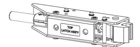
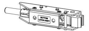
4600 CVR Top Latch Assembly (available as a replacement part) Contains 1 4600 CVR Top Latch Assembly. The screws to mount the latch to the door are contained in the 4600 CVR Latch Screw Pack as discussed on the previous page.
4600 CVR Bottom Latch Assembly (available as a replacement part) Contains 1 4600 CVR Bottom Latch Assembly. The screws to mount the latch to the door are contained in the 4600 CVR Latch Screw Pack as discussed on the previous page.
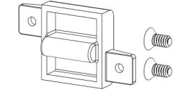
4600 CVR Top Strike Packaged Assembly (available as a replacement part) Contains 1 4600 CVR Top Strike and 2 #10-24 Phillips Flat Head Machine Screws used to fasten the strike to the frame.
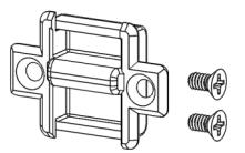
4600 CVR Bottom Strike Packaged Assembly (available as a replacement part) Contains 1 4600 CVR Bottom Strike and 2 #10-24 Phillips Flat Head Machine Screws used to fasten the strike to the threshold.
1. PREPARE THE DOOR
- A. Mark the horizontal centerline of the device by drawing a line across the door at 40" off the finished floor. See Door Prep Drawing (T-ED01910) for more information.
- B. Mark the backset line and two mounting holes for the chassis using the template.
- C. Prepare door, frame and threshold cutouts as shown in the Door Prep Drawing (T-ED01910).
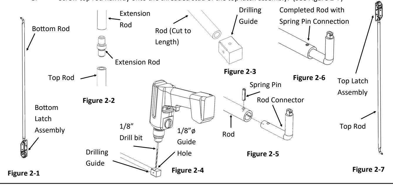
2. ASSEMBLE RODS AND LATCHES
BOTTOM ROD (FOR LESS BOTTOM ROD [CLB] DEVICES, SKIP THIS STEP.)
- A. Screw the bottom rod halfway onto the threaded stud on the bottom latch assembly. (See Figure 2-1)
- B. The bottom rod is pre-sized for a device mounted 40" off the finished floor. If necessary, the bottom rod can be cut down by removing the top rod connector and cutting the rod following the steps in the top rod section.
TOP ROD
- A. For a non-standard door height, cut the rod to length. Be sure to cut the unthreaded side of the rod and deburr edges. For a door of standard height proceed to step E.
- B. For devices being used on doors of 10 foot height, the top rod comes in two pieces. Connect the two ends using the extension rod connector. (See Figure 2-2)
- C. Slide the rod into the drilling guide, making sure the rod is fully inserted into the guide. (See Figure 2-3)
- D. Lay the rod with the drilling guide flat on a table. Use one of the existing 1/8" guide holes on any side of the drilling guide to drill a 1/8" hole through the rod. (See Figure 2-4)
- E. Slide the rod connector into the newly drilled end of the rod. Line up the hole in the rod connector with the hole that was just drilled in the rod. (See Figure 2-5)
- F. Use a hammer to tap the provided spring pin into the hole until it is fully seated. Check for a secure connection between rod and rod connector. (See Figure 2-6)
- G. Screw top rod halfway onto the threaded stud of the top latch assembly. (See Figure 2-7)

3. INSTALL LATCHES
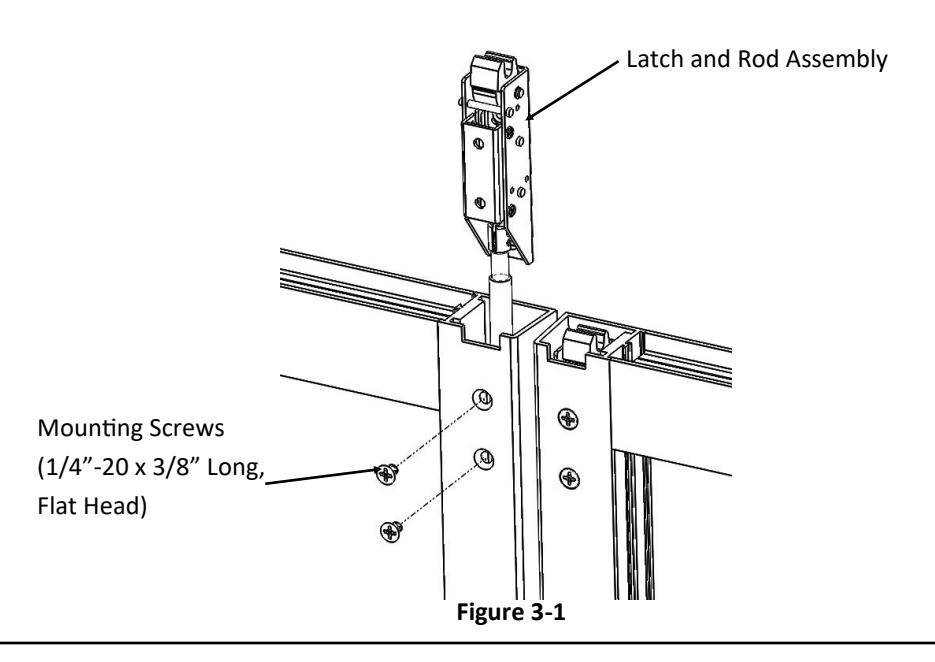
- A. Insert the top latch and rod assembly into the door. Fasten the top latch to the door using the supplied screws. (See Figure 3-1)
- B. Insert the bottom latch and rod assembly into the door. Fasten the bottom latch to the door using the supplied screws. (Skip this step for Less Bottom Rod [CLB] devices.)
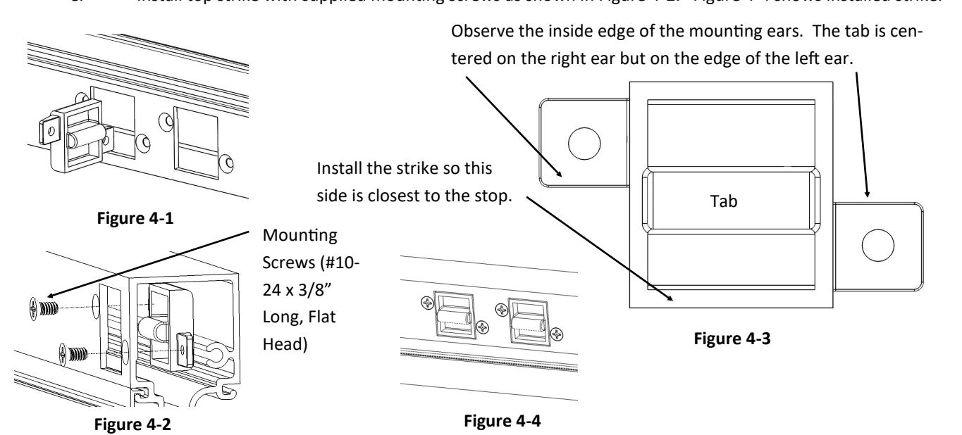
4. INSTALL TOP STRIKE
- A. Install top strike by turning it and inserting into the hole in the header. (See Figure 4-1 and 4-2)
- B. The top strike tab is slightly off-center relative to its mounting holes. (See Figure 4-3) This is for adjustment purposes. Install the top strike so the tab is toward the stop as shown in Figure 4-3.
- C. Install top strike with supplied mounting screws as shown in Figure 4-2. Figure 4-4 shows installed strike.
Rev 3, Rev Date: 2/13/20 Page 5 of 10

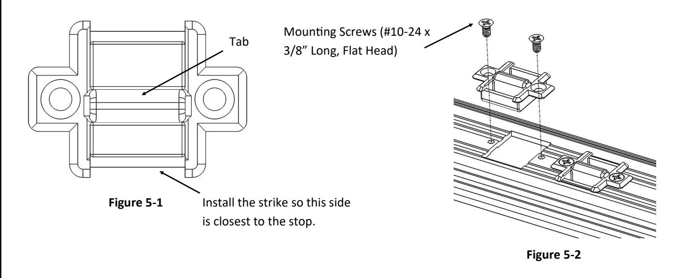
5. INSTALL BOTTOM STRIKE (FOR LESS BOTTOM ROD [CLB] DEVICES, SKIP THIS STEP AND PROCEED TO STEP 6)
- A. The bottom strike tab is also off-center relative to its mounting holes. (See Figure 5-1) This is for adjustment purposes.
- B. Insert the top strike so the tab is toward the stop as shown in Figure 5-1.
- C. Install the top strike with supplied mounting screws as shown in Figure 5-2.
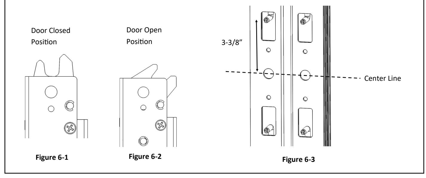
6. ADJUST RODS TO APPROXIMATE POSITION
- A. Ensure all latches are in the Door Closed Position. (See Figures 6-1). If the latch is in the Door Open Position, manually push it back into the Door Closed position. (See Figure 6-2) Be careful to avoid sharp corners on the door notch when moving the latch.
- B. The distance between the horizontal centerline and the center hole of the rod connectors should be 3-3/8". (See Figure 6-3) Adjust this distance by turning the rod connector inside the door, therefore screwing or unscrewing the rod further on the latch. Make this adjustment for both the top and bottom rods.

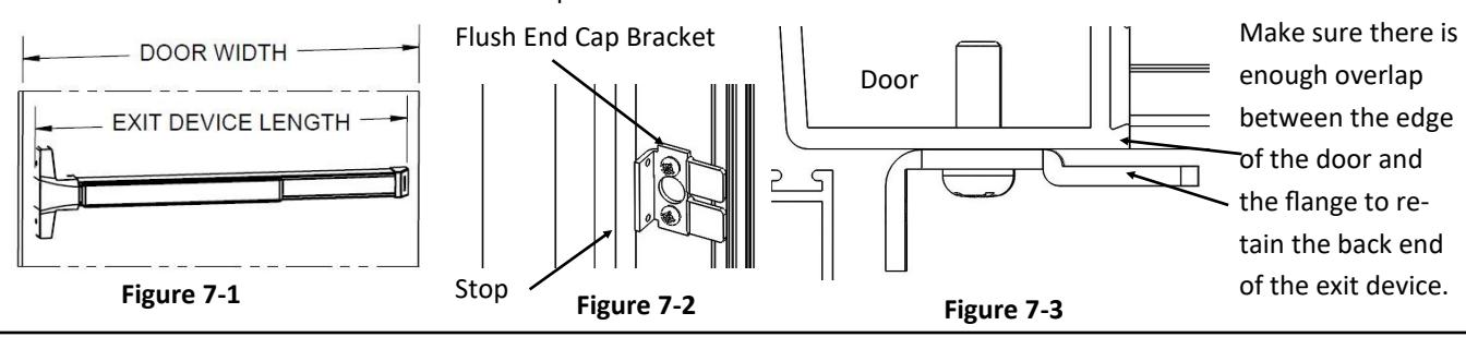
7. CUT DEVICE TO LENGTH AND MOUNT FLUSH END CAP
- A. The exit device comes in two lengths, one sized for a 36" door width and one sized for a 48" door width. For other door widths, cut the exit device to appropriate length. Recommended overall length of the exit device is equal to the door width minus 1 inch. (See Figure 7-1) Make sure the back end of the exit device extends far enough for the flush end cap bracket to reach the hinge stile. (See Figure 7-2) The exit device cover tube slides between the flush end cap bracket and the door. Make sure there is enough overlap between the flanges in the flush end cap bracket and the door to retain the exit device. (See Figure 7-3) Cut with hack saw or metal cutting saw blade. Make sure cut is straight or the end cap won't sit flush. Deburr edges.
- B. Prepare End Cap Mounting screw holes. For surface mounting, drill and tap 1/4"-20. For thru bolting, drill 5/16" clearance holes on push side and 3/8" clearance holes on pull side. Install flush end cap bracket and flush end cap. If flush end cap is not flush with the device, remove the flush end cap and loosen the mounting screws and move the flush end cap bracket towards the device as needed.
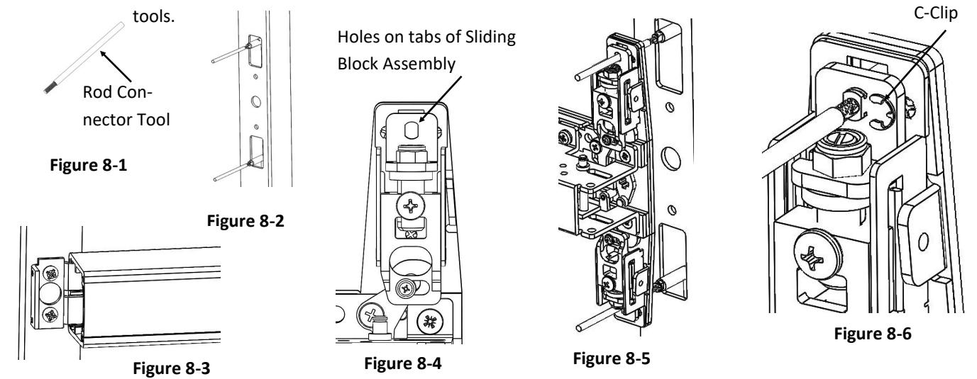
8. ATTACH DEVICE TO ROD CONNECTORS
- A. Screw the supplied rod connector tools into both rod connectors. (See Figures 8-1 and 8-2)
- B. Insert the end of the exit device into the end cap bracket to help hold the back end. (See Figure 8-3)
- C. Position the exit device head so the rod connector tools protrude through the holes on the tabs of the sliding block assembly. (See Figures 8-4 and 8-5)
- D. Position the exit device flush against the door.
- E. Pull the rod connectors through the holes on the tabs of the sliding block assembly using the rod connector tools. (See Figure 8-6)
- F. Install provided c-clips in the slots on the rod connectors. (See Figure 8-6). Remove rod connector
Rev 3, Rev Date: 2/13/20 Page 7 of 10

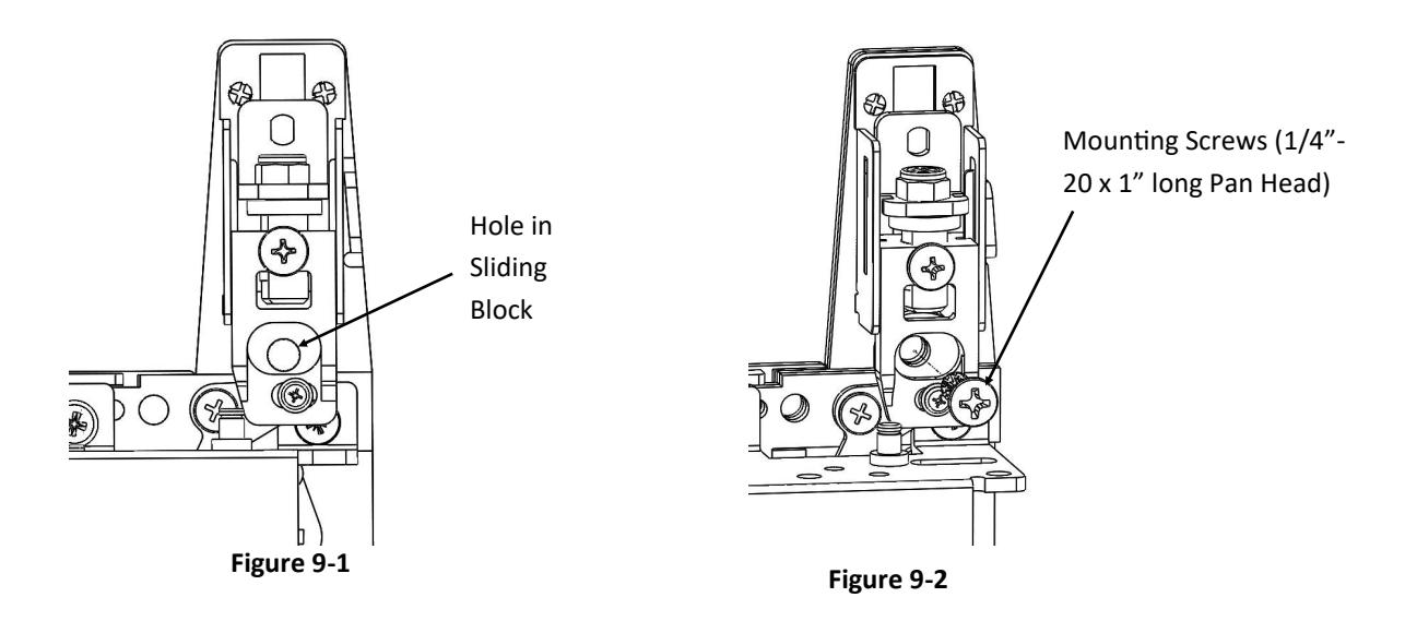
9. ATTACH DEVICE TO DOOR OR TRIM
- A. Press the push bar to retract sliding blocks.
- B. Insert the provided mounting screws through the hole in the sliding blocks and through the exit device base plate.
- C. Tighten screws to posts in trim, sleeve nuts or threaded holes in door depending on your application.
10. HANG DOOR
A. Install the door in the frame or move to an upright position to test latches.
11. TEST OPERATION
A. Ensure the all latches are in the Door Closed Position. (See Figures 11-1). If the latch is in the Door Open Position, manually push it back into the Door Closed Position. (See Figure 11-2) Be careful to avoid sharp Corners on the door notch moving the latch. If the latches do not move to the proper Door Closed Position, loosen the adjustment locking screw and unscrew the fine adjustment screw by one-half turn. Continue unscrewingthe fine adjustment screw until the latches are able to move into the Door Closed Position.
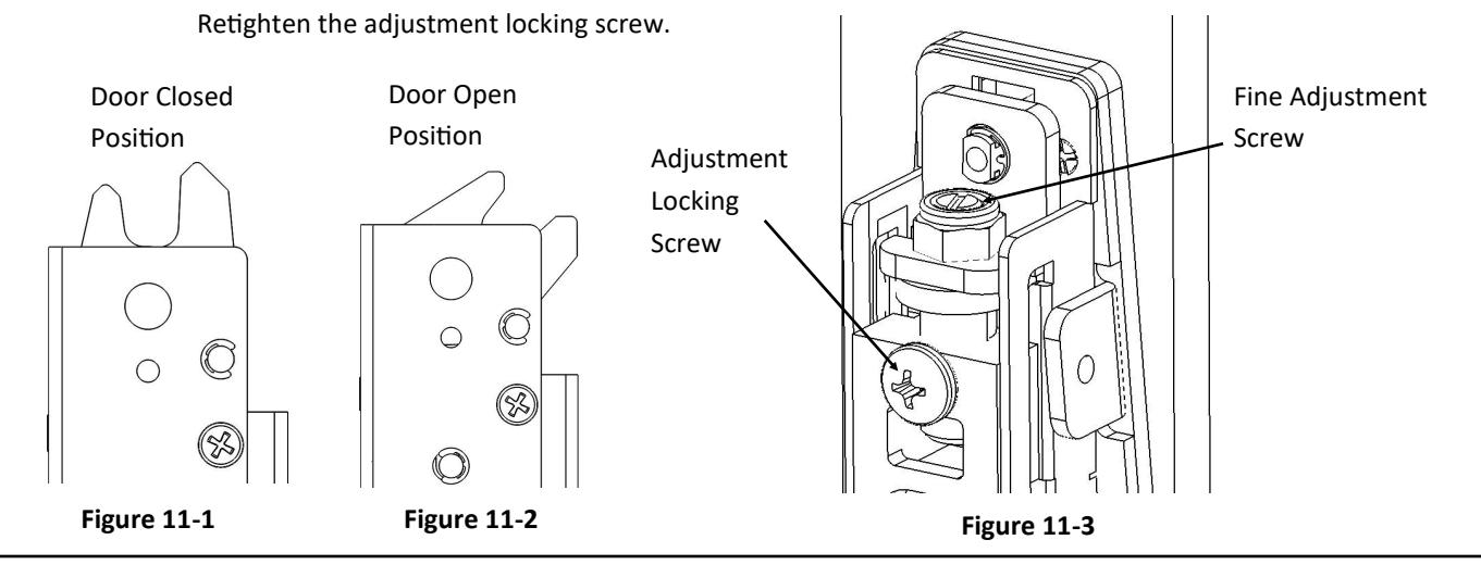
11. TEST OPERATION (CONTINUED)
- B. The latches should be in the Door Closed Position. (See Figure 11-1) Press the push bar. The latches should move to the Door Open position and stay there. (See Figure 11-2) When adjusted properly, both latches will release at the same time when the push bar is pressed. If the latches do not move and stay in the Door Open Position, loosen the adjustment locking screw and screw in the fine adjustment screw by one -half turn. (See Figure 11-3) Press the push bar again. If the latches do not move into the Door Open Position continue screwing in the fine adjustment screw by one half turn and pressing the push bar until the latches are able to move into the Door Open Position. Retighten the adjustment locking screw.
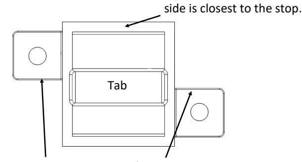
- C. Test the operation by shutting the door. When the door is shut, the latches should rotate fully into the Door Closed Position. If the latches do not go fully into the Door Closed Position, check to see if the door is flush against the stop. If the door is flush against the stop and the latches cannot go into the Door Closed Position, try turning both strikes 180 degrees. This will move the tab 1/16" further from the stop. (See Figure 11-4 and 11-5) Unscrew the strikes, turn them 180 degrees so the tab is now facing the other direction. Reinstall the strikes. Shut the door to see if the latches rotate fully into the Door Closed Position.
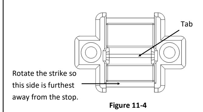
Rotate the strike so this
Observe the inside edge of the mounting ears. The tab is centered on the right ear but on the edge of the left ear.
Figure 11-5
- D. If the door is not flush against the stop and the latches cannot go into the Door Closed Position, try unscrew ing the fine adjustment screw as described in step A of this section.
- E. If the door is difficult to open when the push bar is pressed, try screwing in the fine adjustment screw as described in step B of this section. This may need to be done for both or either latches depending on which one seems to be preventing the door from opening.
- F. When the device is working properly, reinstall the head cover with supplied screws.
Rev 3, Rev Date: 2/13/20 Page 9 of 10
12. DOGGING DEVICE
- A. For increased life of the device, dog the push bar down during high traffic periods of the day. Dogging is not available on fire-rated models.
- B. Hex Wrench Dogging:
To dog the device, press the push bar, insert the hex dogging wrench and turn clockwise 35 degrees. The push bar will remain depressed and the latch will stay in the Door Open Position. (See Figure 12-1) To re lease the dogging, hold the push bar down, insert the hex dogging wrench and turn counter-clockwise 35 de grees. The push bar will return to the up position and the latch will actuate to lock the door.
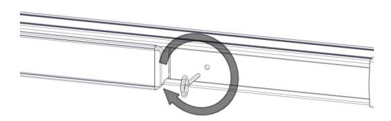
Figure 12-1
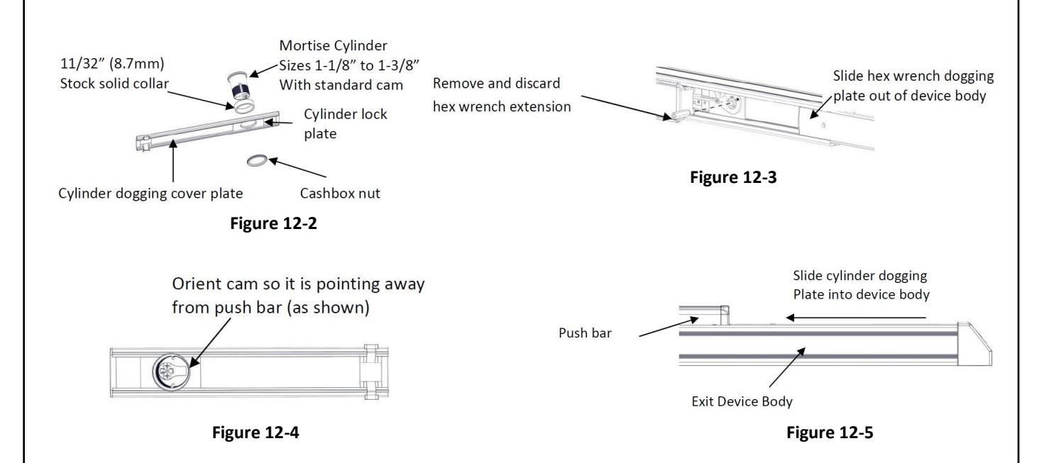
C. Cylinder Dogging:
Required hardware for cylinder dogging includes one (1) mortise cylinder, lengths 1-1/8", 1-1/4" or 1-3/8" with a standard cam (0.723" [18mm] screw center to tip of cam): and one (1) Hager Cylinder Dogging kit (4925C) which includes one (1) 11/32" [8.7mm] solid cylinder collar and cashbox nut. (See Figure 12-2) Remove and discard the hex wrench extension. (See Figure 12-3) The cylinder should be oriented so the cam is pointing away from the exit device push bar. (See Figure 12-4) Install the dogging cover plate with the cylinder and test the dogging. (See Figure 12-5) Depress the push bar, insert the key and turn the key clockwise to dog the device. Turn the key counter-clockwise to release the dogging.