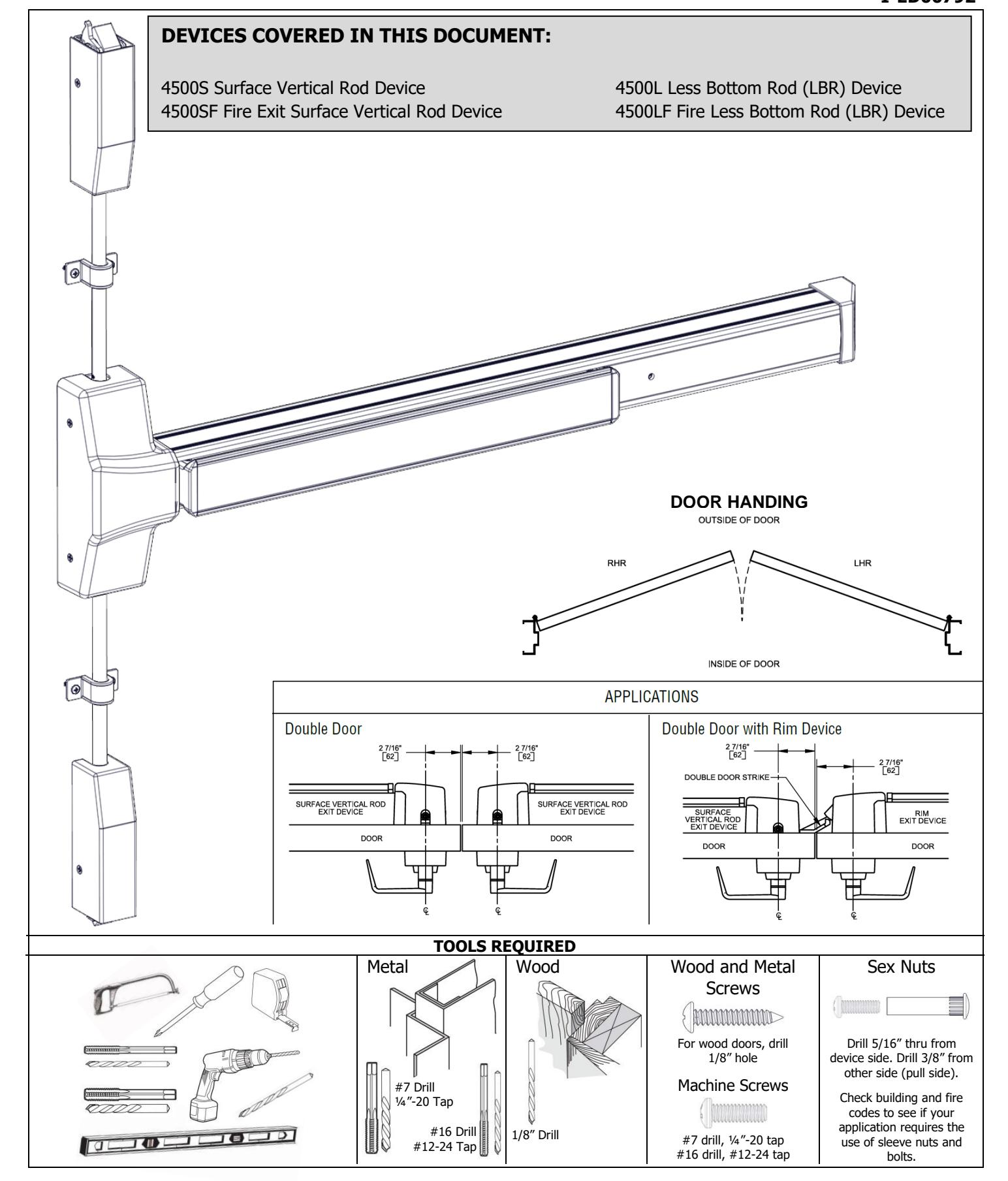
4502 Series SVR Installation Instructions – I-ED00792
Open the original PDF document
View PDF


Rev 10, Rev Date: 12/12/2024 Page 2 of 13

LBR DEVICE NOTES
LBR devices require the following additional components to maintain fire rating:
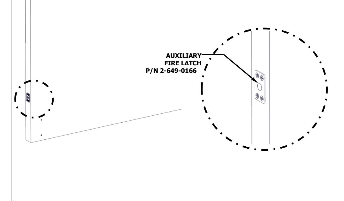
- One Fire Bolt per pair of doors is required P/N 2-649-0166
- Head Cover Hole Plug P/N 26490167
Important Fire Listing Notes: READ THIS FIRST!
- Fire rated devices must be ordered and installed in pairs of vertical rod devices or can be used in conjunction with an approved automatic or constant latching flush bolt.
- The auxiliary fire latch will keep the doors in alignment during a fire when the bolt extends from the auxiliary fire latch into the strike hole in the opposite door. For the auxiliary fire latch bolt to extend into the strike hole, the black cap visible on the face of the auxiliary fire latch and the strike hole must melt. Therefore, do not cover the door gap directly in front of the auxiliary fire latch with a door edge guard or any other similar type of device.
• A double door application consists of two LBR devices and one auxiliary fire latch. The auxiliary fire latch should be installed in the inactive door to maintain fire listing.
- The auxiliary fire latch is only for use with the Hager 4500 Series LBR devices. The 4500 Series LBR device comes with a standard top latch strike (4923F), which must be utilized to maintain fire listing.
- Refer to the Auxiliary Fire Latch Installation Instructions (I-ED00863) for further details.
LBR DEVICE
Rev 10, Rev Date: 12/12/2024 Page 3 of 13

The exit device comes in two models, one sized for a 36" door width and one sized for a 48" door width. For other door widths, cut exit device to appropriate length. Recommended overall length of the exit device is equal to door width minus 4 inches. Cut with hack saw or metal cutting saw blade. Deburr edges.
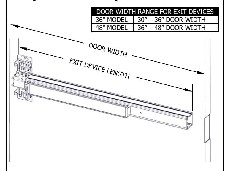
RECOMMENDED EXIT DEVICE LENGTH=DOOR WIDTH – 4"
1. CUT EXIT DEVICE TO LENGTH 2. MARK DOOR AND DRILL MOUNTING HOLES
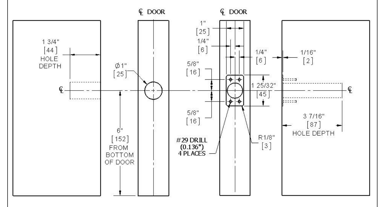
Measure horizontal center line of exit device at 40" from finished floor. Apply template to door using centerline and edge of door. Mark and drill holes as shown on template. Be sure the vertical centerline for the exit device mounting holes is 2 7/16" from the edge of the door or stop face (door edge shown).
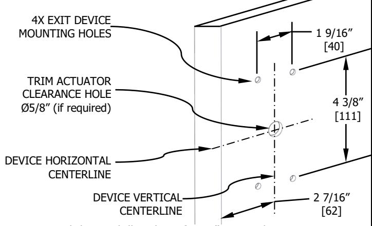
- For metal doors, drill and tap for ¼"-20 machine screws
- For wood doors, pre-drill 1/8" holes
- If mounting trim, drill 5/16" clearance holes on exit device side of door (push side) and ½" holes on pull side. Trim requires an additional 5/8" clearance hole for the trim actuating shaft.
- If using Sex Nuts, drill 5/16" clearance holes on exit device side of door (push side) & 3/8" on pull side
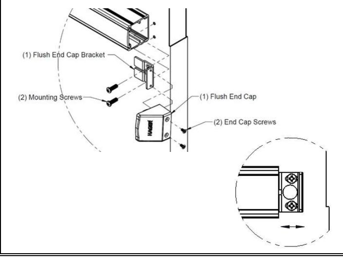
3. INSTALL EXIT DEVICE 4. INSTALL END CAP
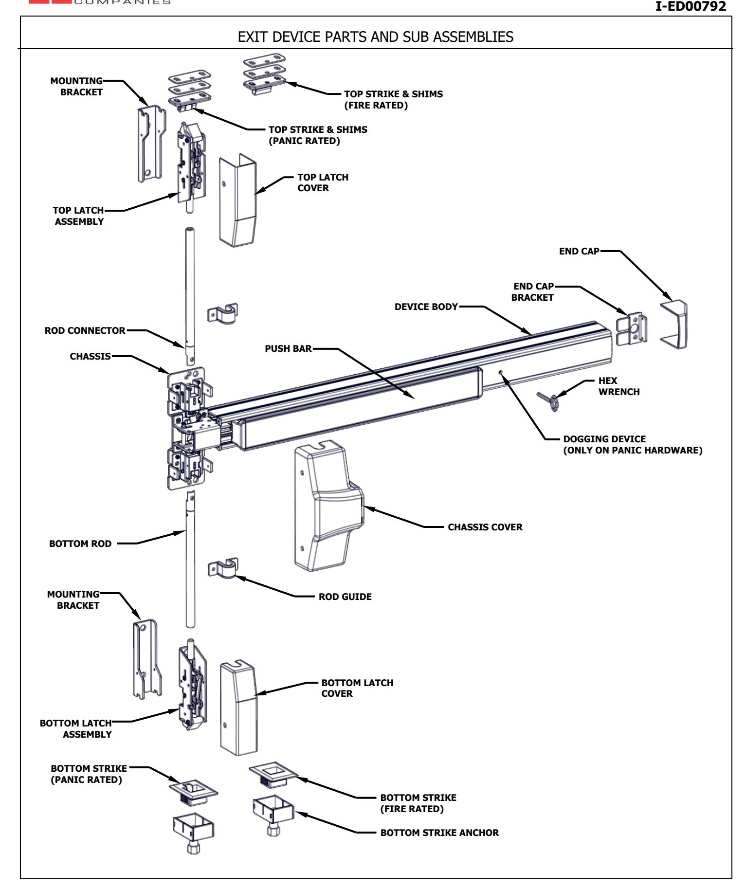
Remove head cover from exit device chassis. Mount exit device using the 4 mounting holes indicated on template.
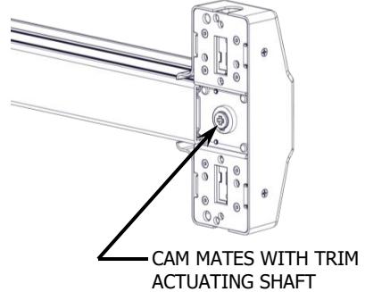
If using trim, be sure to line up trim actuating shaft (tailpiece) with cam located on back of exit device chassis.
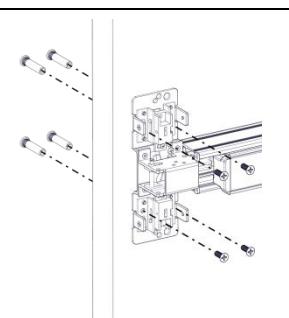
Screws:
Metal door, Sex Nuts, or Trim: 1/4"-20 machine screws (4)
Wood door: #12 wood screws (4)
Remove the flush end cap from the flush end cap bracket. Mark hole locations by holding flush end cap bracket up against door and device. Be sure exit device is level before inserting the flush end cap bracket into the device. Mark and drill/tap holes. Install flush end cap bracket and flush end cap using supplied screws. If the flush end cap is not flush with the exit device, remove flush end cap and adjust the mounting screws and the flush end cap bracket as needed.
3 7/32" [82]
1 3/32" [28] (SEE NOTE 2)
2 7/16" [62] (SEE NOTE 1)
LATCH MOUNTING BRACKET

5. INSTALL BOTTOM LATCH MOUNTING BRACKET (FOR LBR DEVICE, GO TO STEP 8)
Remove bottom latch cover and mounting bracket from bottom latch assembly. Apply template to door using edge of door and either top of threshold or finished floor. Mark and drill holes as shown on template. If using bottom strike, use template to mark location for bottom strike anchor. Be sure the vertical centerline for the bottom latch mounting holes is 2 7/16" from the edge of door. Install bottom latch mounting bracket.
- For metal doors, drill and tap for 1/4"-20 machine screws
- For wood doors, pre-drill 1/8" holes
- For Sex Nuts, drill 5/16" clearance holes on exit device side (push side) and 3/8" on pull side.
Screws:
Metal door or Sex Nuts: 1/4"-20 machine screws (1)
Wood door: #12 wood screws (1)
NOTE:
- 1. THIS DIMENSION IS MEASURED FROM THE DOOR EDGE OR STOP FACE, DEPENDING UPON THE APPLICATION (DOOR EDGE SHOWN). THIS SHOULD LINE UP WITH VERTICAL EXIT DEVICE AND TOP STRIKE CENTERLINES.
- 2. THIS DIMENSION ASSUMES A 3/8" GAP FROM DOOR EDGE TO FINISHED FLOOR.
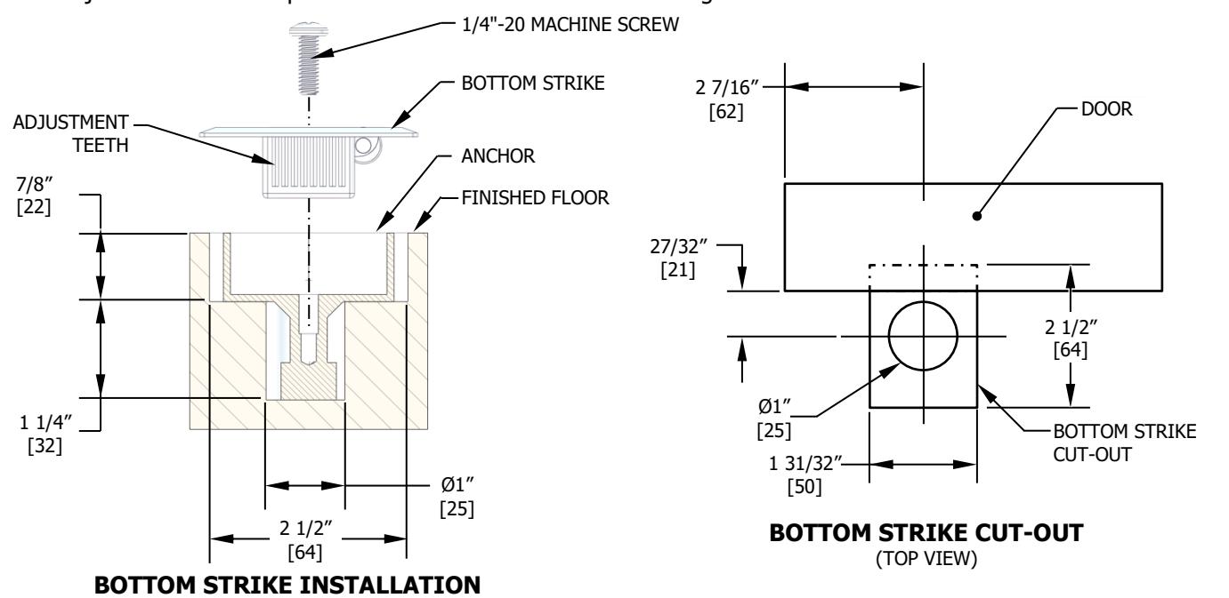
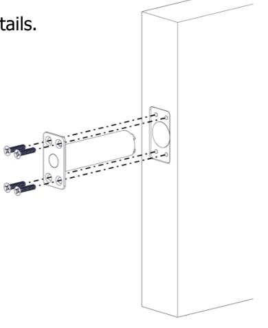
6. INSTALL BOTTOM STRIKE (Skip this step if using a panic threshold)
- STEP 1: Bottom strike anchor location should already be marked. If not, extend bottom latch mounting bracket centerline to finished floor or threshold
- STEP 2: Cut out hole in finished floor or threshold for bottom strike. The hole depth should be 7/8" deep.
- STEP 3: At bottom of the strike cutout, mark and drill Ø1" by 1 1/4" deep hole for anchor.
- STEP 4: Fill with grout and insert anchor to acquire flush and level floor.
- STEP 5: Insert bottom strike into anchor and secure with machine screw.
Screws: 1/4"-20 machine screw and anchor assembly
NOTE: Adjustment teeth are provided on bottom strike for fine tuning the bottom strike distance from the door face.
Rev 10, Rev Date: 12/12/2024 Page 5 of 13

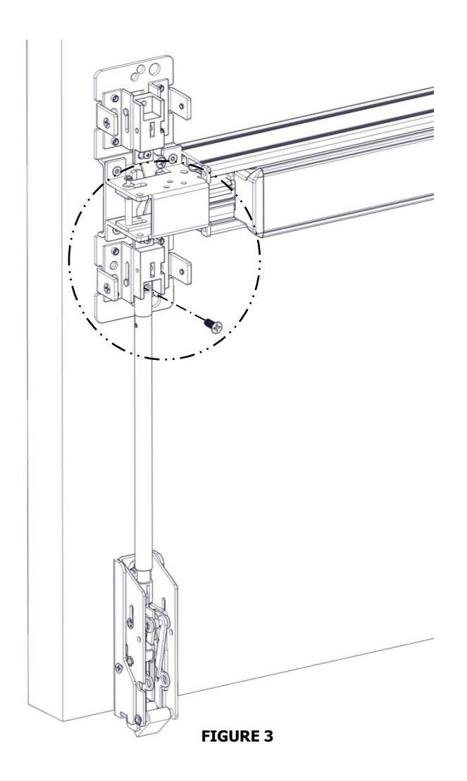
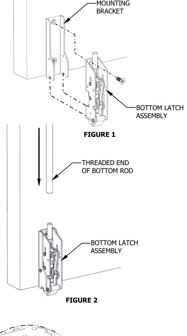
7. INSTALL BOTTOM LATCH AND ROD
- STEP 1: Install bottom latch assembly to bottom latch bracket using provided screws and bottom two slots in bracket (see Figure 1).
- STEP 2: Screw threaded end of bottom rod halfway onto bottom latch assembly (see Figure 2).
- STEP 3: Align the top end of the bottom rod with the actuating block (see Figure 3). Align by rotating rod clockwise or counterclockwise until the holes line up (see Detail A).
- STEP 4: Use the provided machine screw to attach rod to actuating block. Be sure actuating block on the chassis is in the down position (see Detail A).
CHECK INSTALLATION by pushing on exit device push bar. Make sure bottom latch is retracted when push bar is depressed. Bottom latch should clear the finished floor, strike, or threshold. Bottom latch should have 1/2" throw.
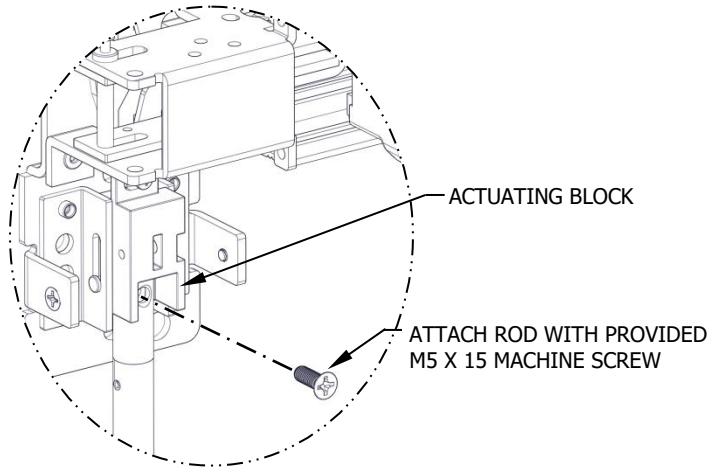
DETAIL A

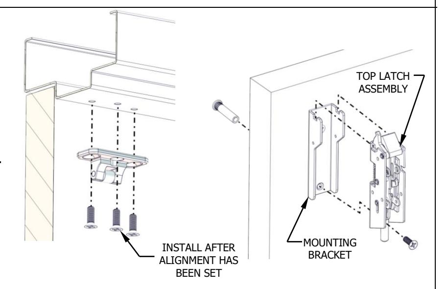
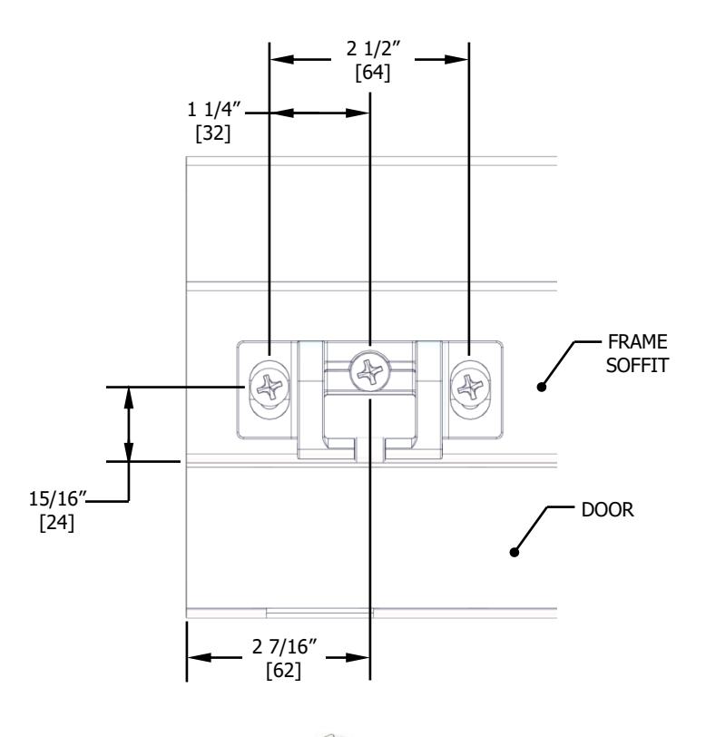
8. INSTALL TOP MOUNTING BRACKET (FOR 10 FT. FIRE RATED DEVICE, GO TO STEP 10)
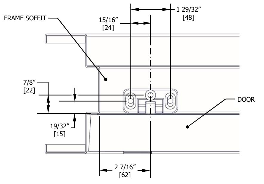
Remove top latch cover and mounting bracket from top latch assembly. Fold and apply template to door using edge of door and face of top stop. Mark and drill holes as shown on template for both top latch bracket and strike. Be sure the vertical centerline for the top latch mounting holes are 2 7/16" from the edge of door or the stop face (door edge shown). Install top mounting bracket. This should line up with exit device and top strike centerlines.
- For metal doors, drill and tap for 1/4"-20 machine screw
- For wood doors, pre-drill 1/8" hole
- For Sex Nuts, drill 5/16" clearance hole on exit device side (push side) and 3/8" on pull side
3 1/4" [82] 2 29/32 [74] TO DOOR EDGE 2-3/8" [60] TO FACE OF STOP
Screws :
Metal doors or Sex Nuts: 1/4"-20 machine screw (1) Wood door: #12 wood screw (1)
9. INSTALL TOP LATCH AND STRIKE
- STEP 1: Install top strike to face of stop using only the two outer slotted mounting holes.
- STEP 2: Install top latch assembly to top mounting bracket using provided screws and top two slots in bracket.
- STEP 3: Close door, check alignment of strike and top latch, adjust if required, and install screw into center hole in strike.
- For metal stop, drill and tap for #1/4-20 machine screws
- For wood stop, pre-drill 1/8" holes
Strike Screws :
Metal Stop:
#1/4-20 flat head machine screws (3) Wood Stop:
#12 flat head wood screws (3)

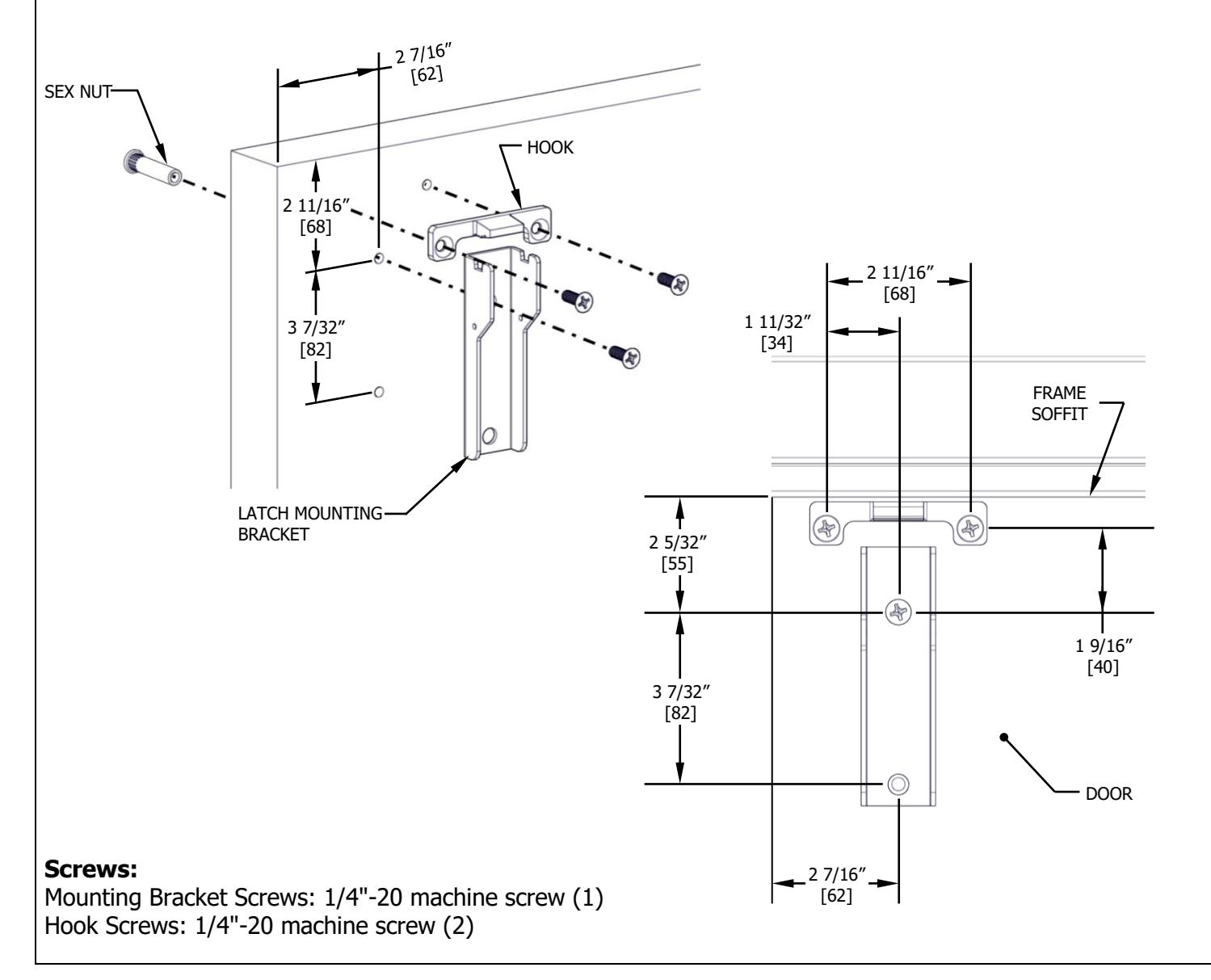
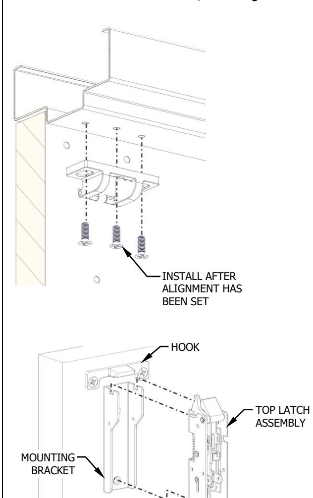
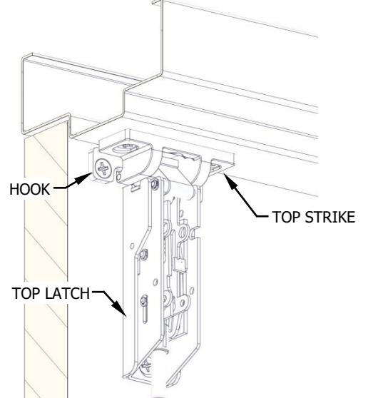
10. INSTALL TOP MOUNTING BRACKET AND HOOK (FOR 10 FT. FIRE RATED DEVICE ONLY)
- STEP 1: Remove top latch cover and mounting bracket from top latch assembly.
- STEP 2: Fold and apply template to door using door edge and face of top stop.
- STEP 3: Mark and drill holes as shown on template for the top latch bracket, hook, and strike. Be sure the vertical centerline for the top latch mounting holes is 2 7/16" from the door edge or stop face (door edge shown). Make sure the centerline of the strike mounting holes line up with the vertical exit device and bottom latch centerlines.
- STEP 4: Install top mounting bracket and hook.
-
Metal Doors:
- Sex Nuts: Drill Ø5/16" clearance holes on exit device side (push side) and Ø3/8" on pull side
- Surface Mounting: Drill and tap for #1/4-20 machine screws
-
Wood Doors: Sex Nuts are required on fire rated wood doors.
- Sex Nuts: Drill a Ø3/8" through hole
Rev 10, Rev Date: 12/12/2024 Page 8 of 13

11. INSTALL TOP LATCH AND STRIKE (FOR 10 FT. FIRE RATED DEVICE ONLY)
- STEP 1: Install top strike to face of stop using only the two outer slotted mounting holes.
- STEP 2: Install top latch assembly to top mounting bracket using provided screw and two slots in bracket.
- STEP 3: Close door, check alignment of strike and top latch, adjust if required, and install screw into center hole in strike.
-
Metal Doors:
- Sex Nuts: Drill Ø5/16" clearance holes on exit device side (push side) and Ø3/8" on pull side
- Surface Mounting: Drill and tap for #1/4-20 machine screws
-
Wood Doors: Sex Nuts Required
- Sex Nuts: Drill a Ø3/8" through hole

Top Strike Screws: 1/4"-20 machine screw (3) Latch Screws: 1/4"-20 machine screw (1)

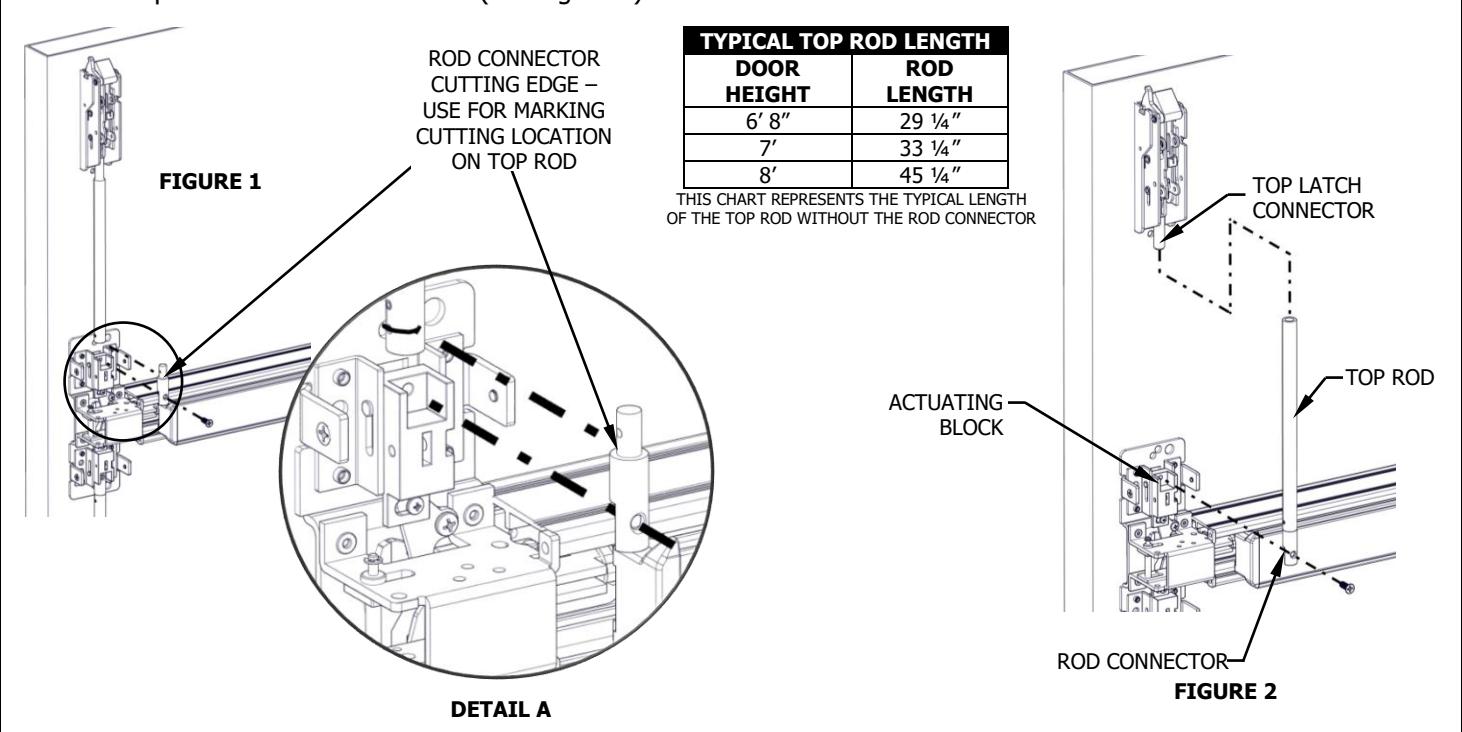
12. INSTALL TOP ROD
- STEP 1: Thread top rod half-way onto top latch threaded connector (see Figure 1).
- STEP 2: Use the provided machine screw to attach rod connector onto actuating block, but do not attach top rod to rod connector yet. Align the edge of rod connector next to top rod and mark a cutting line on top rod, if necessary (see step 12.1 Cut Rod to Length). Be sure the top latch is not actuated and exit device push bar is not depressed (see Figure 1).
- STEP 3: Be sure top latch is in the locked position (not retracted). If rod required cutting in step 2, rethread top rod half-way onto top latch threaded connector. Fasten bottom end of top rod onto actuating block on exit device chassis. This may require raising or lowering the top rod by threading it clockwise or counterclockwise on the top latch threaded connector (see Figure 2).
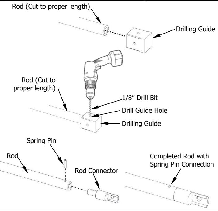
12.1 CUT ROD TO LENGTH (ONLY REQUIRED FOR NON-STANDARD DOOR HEIGHT)
- STEP 1: Remove top rod and cut top rod with hack saw or metal cutting saw blade. Deburr edges.
- STEP 2: Slide newly cut rod into drilling guide until it stops. Drilling guide sets the hole location so be sure rod is fully inserted.
- STEP 3: Lay the rod with drilling guide flat on a table. Use one of the existing 1/8" guide holes on any side of the drilling guide and drill an 1/8" hole through the rod.
-
STEP 4:
Install rod connector:
- a. Slide the rod connector into the newly drilled end of the rod and line up the hole in the rod connector with the hole that was just drilled into the rod.
- b. Use a hammer to tap the provided spring pin into the hole until it is fully seated. Check that there is a secure connection between the rod and rod connector.
Rev 10, Rev Date: 12/12/2024 Page 10 of 13

13. ADJUST AND TEST INSTALLATION
EXIT DEVICE OPERATION
When push bar is depressed and the door is opened, the top and bottom latches should be held retracted until door closes. When the push bar is released both latches remain in the retracted state. When the door closes and the top latch engages with the top strike, it releases the holding mechanism and allows the bottom latch to fully extend.
If the latches do not work smoothly when opening and closing the door, adjust the rod accordingly:
| Problem | Try This |
|---|---|
| If the bottom latch does not clear the strike or threshold |
Disconnect the bottom rod from the actuating block and thread
the rod farther into the bottom latch. This will raise the rod further when the device is activated, retracting the latch bolt farther, locking it into the latched position. |
| If the top latch does not clear the strike |
Disconnect the top rod from the actuating block and thread the
rod into the latch, which will shorten the overall distance. This will allow the top latch to completely retract out of the way of the strike, locking into the latched position. |
| If the top latch does not operate smoothly |
Perform the steps noted above. Also try threading the rod into
the latch farther if required. |
|
If the latches are not staying retracted when the door is
opened |
The top latch may be too far away from the top strike. Insert
one top strike shim underneath the top strike to move it closer to the latch and test operation. If the problem continues, insert the second provided shims |
| underneath the top strike |
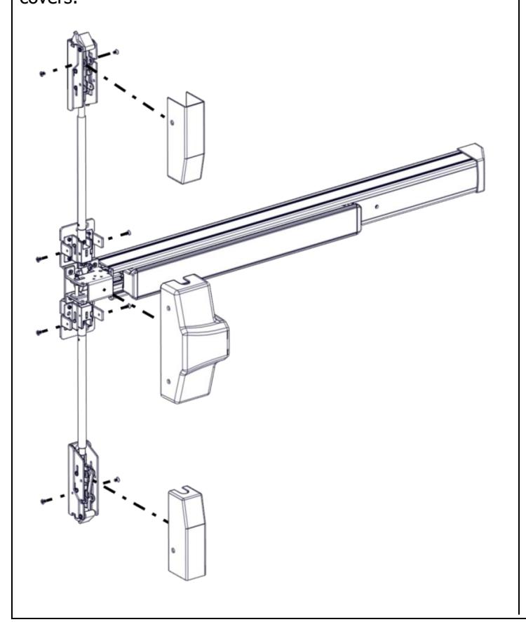
14. INSTALL COVERS
Install chassis head cover and both top and bottom latch covers.
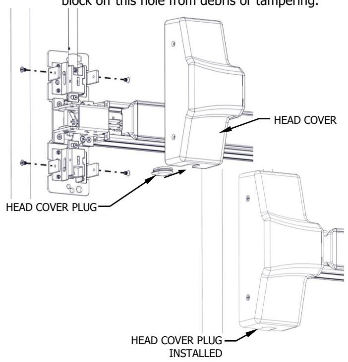
Install Head Cover Plug (FOR LBR DEVICES ONLY):
STEP 1 : Slide the head cover plug into the bottom slot on the exit device head cover. Since the LBR does not use a bottom rod, the hole plug will block off this hole from debris or tampering.
Rev 10, Rev Date: 12/12/2024 Page 11 of 13

15. INSTALL ROD GUIDES
Install top and bottom rod guides centered between latch cover and head cover or at desired height. SCREWS: Metal Door: 8-32 machine screws (4) Wood Door: #10 wood screws (4)
16. DOGGING DEVICE
For increasing the life of this device, dog device during high traffic periods of the day. (A dogging device is not available on fire rated models).
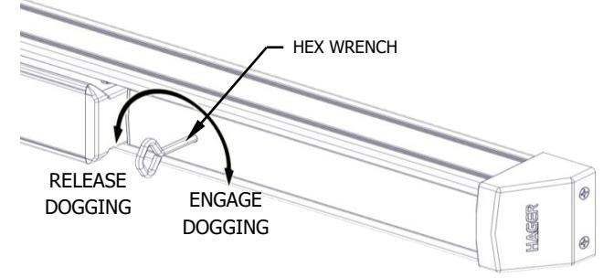
Hex Wrench Dogging:
- Engage Dogging: Depress push bar, then insert dogging hex wrench and turn clockwise 35°. The push bar will remain depressed and the latch will stay retracted.
- Release Dogging: Hold push bar, insert dogging hex wrench and turn counterclockwise 35°. The push bar will return to the up position and latch will extend to lock door.
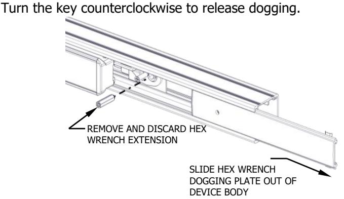
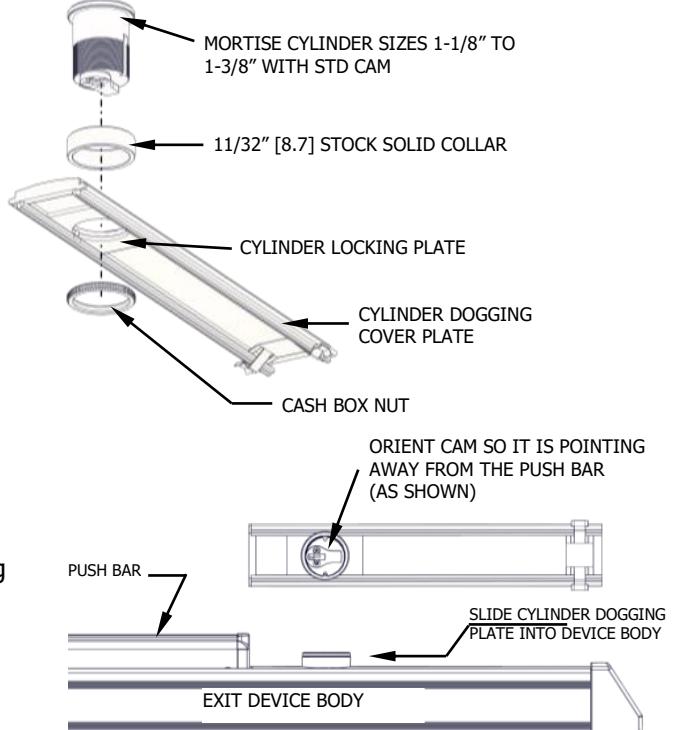
Cylinder Dogging:
For cylinder dogging, remove the cover plate. Remove the hex wrench extension located below the dogging cover plate, which is held in place by a magnet. Install a mortise cylinder into the cylinder dogging cover plate using an 11/32" [8.7] solid cylinder collar and cash box nut. On the mortise cylinder, use a "standard cam" (.723" [18], screw center to tip of cam). The cylinder should be oriented so the cam is pointing away from the exit device push bar. Install the dogging cover plate with cylinder and test dogging. Depress the push bar, insert key, and turn the key clockwise to dog device.
Required Hardware for cylinder dogging:
-
Mortise Cylinder with Standard Straight Cam (1)
- Cylinder Lengths: 1 1/8", 1 1/4", or 1 3/8"
- Cam center to tip: 0.723" [18]
-
Hager Cylinder Dogging Kit (No. 4926) (1)
- Dogging Cover Plate with Plastic Insert, Spring clip, & Cylinder Dogging Lock Plate (1)
-
Solid Cylinder Collar (1)
- 11/32" [7.8] high
- Cash Box Nut (1)
If it is difficult to dog the device properly, disconnect the top rod from the actuating block and rotate the rod counterclockwise which will lengthen the overall distance. This will allow the push bar to be fully depressed which allows the dogging mechanism to securely attach. If this does not work, repeat the same step with the bottom rod.
Rev 10, Rev Date: 12/12/2024 Page 12 of 13

17. INSTALL AUXILIARY FIRE LATCH (FOR LBR DEVICES ONLY)
Step 1: The Auxiliary Fire Latch must be installed to maintain fire listing.
Step 2: Refer to Auxiliary Fire Latch Installation Instructions (I-ED00863) for details.
STRIKE HOLE PLUG ACTIVE DOOR LEAF
AUXILIARY FIRE LATCH INACTIVE DOOR LEAF
Rev 10, Rev Date: 12/12/2024 Page 13 of 13