4500 Series Trim Installation Instructions – I-ED00788
Open the original PDF document
View PDF

CL
DOOR DOOR
CL
DOOR DOOR
CL CL
EXIT DEVICE
RHR LHR
INSIDE OF DOOR

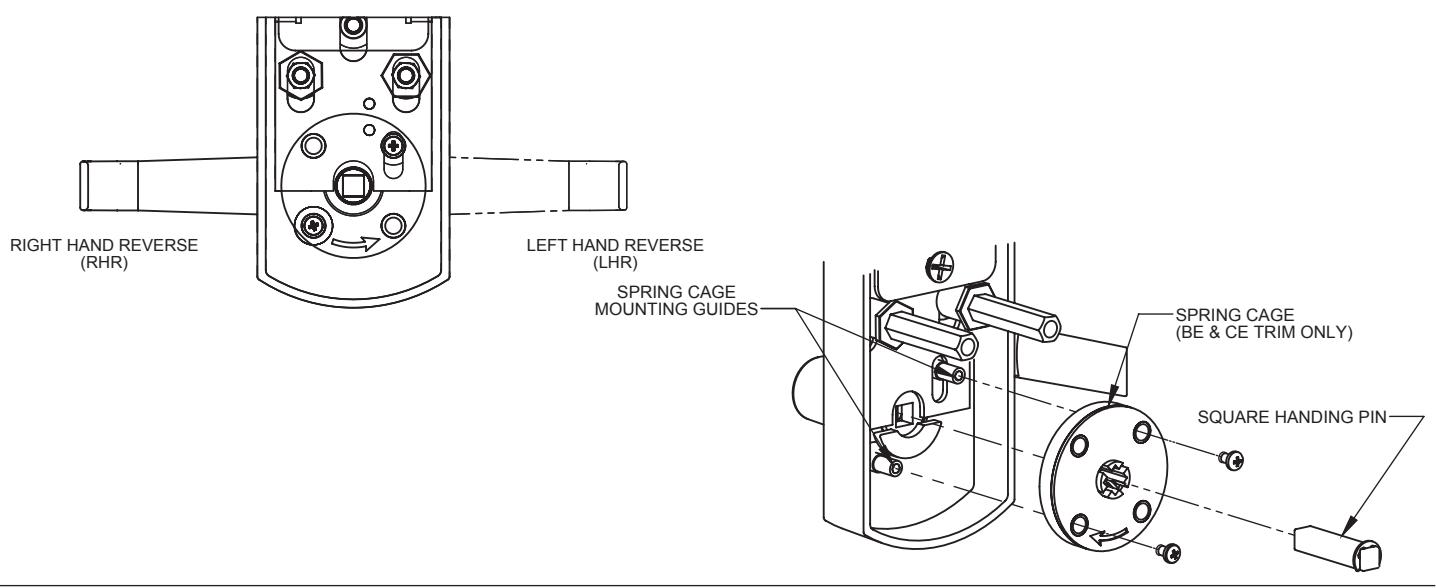
1. SET TRIM HANDING
-
A. Rotate lever handle to the right or left direction to match the desired door handing.
- Skip to step "C" for the Dummy Trim and the Night Latch trim models.
- B. The spring cage is pre-installed for right hand reverse door handing applications (see counterclockwise arrow engraved on face of spring cage). For left hand reverse door handing, remove the two screws holding on the spring cage and flip the spring cage over. You'll see a clockwise arrow engraved on face of spring cage. Reinstall spring cage and secure with screws.
- C. Align the handle for the desired door handing and then insert the square handing pin through the spring cage (or plate) and into the handle.
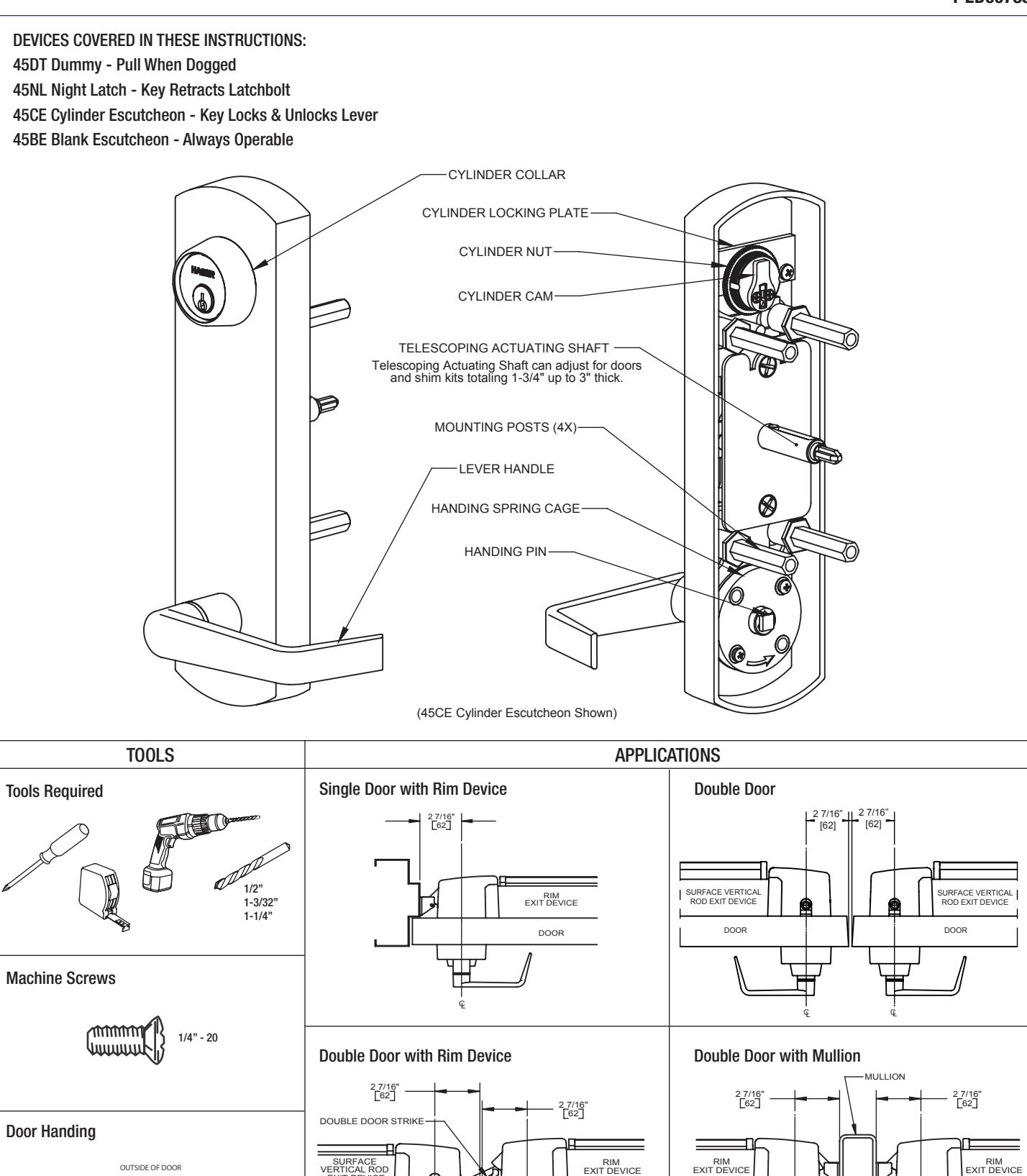
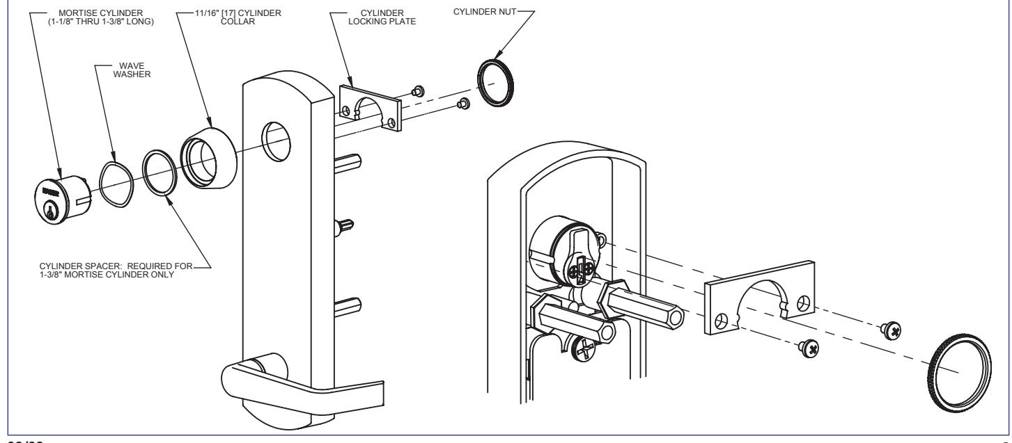
2. INSTALL MORTISE CYLINDER (for CE Trim only)
- A. Remove key from mortise cylinder.
- B. Slide wave washer and cylinder collar onto mortise cylinder body.
- C. Install mortise cylinder into escutheon trim with cam positioned as shown.
- D. Install cylinder locking plate and use provided screws to secure.
- E. Screw cylinder nut onto mortise cylinder until secure.
08/08 2

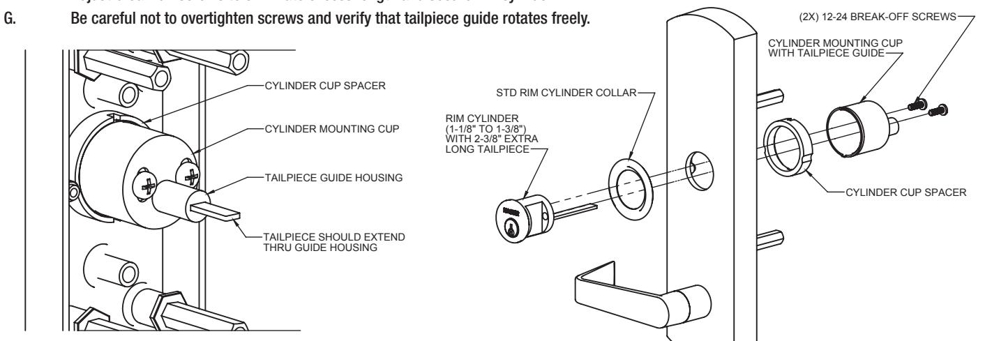
1. INSTALL NIGHT LATCH RIM CYLINDER (for NL Trim only)
- A. Remove key from cylinder.
- B. Replace standard length tailpiece with extra long tailpiece (2-3/8").
- C. Slide cylinder collar onto rim cylinder body.
- D. Install cylinder cup spacer on the back side of the escutheon. Escutheon screw standoffs will fit into the two recesses on the spacer, locking the spacer in place.
- E. Align tailpiece with tailpiece guide and install rim cylinder into escutheon and through the cylinder cup.
- F. Adjust break-off screws to eliminate excess length and secure rim cylinder.
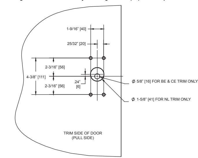
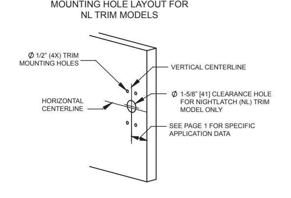
2. MARK AND DRILL MOUNTING HOLES FOR ESCUTHEON TRIM
- A. Mark horizontal centerline by matching it to exit device centerline, which can be found on the push side of door.
- B. Apply template to door using centerline. Refer to Applications section on page 1 to determine the location of the vertical centerline. Vertical centerline should match exit device vertical centerline located on push side of door.
- C. Mark and drill 1/2" holes for mounting posts as shown on template. (Skip to step "E" for Night Latch Trim model.)
- D. Mark and drill a 5/8" hole for trim actuator shaft, which mates with exit device (not required for 45DT). See exit device instructions for further details.
- E. Mark and drill a 1-5/8" hole, centered 0.24" above horizontal centerline, for the Night Latch Trim model only. See Night Latch (NL) Trim template for more details.
MOUNTING HOLE LAYOUT FOR BE, CE & DT TRIM MODELS VERTICAL CENTERLINE 5/8" [13] CLEARANCE HOLE FOR BE & CE TRIM ACTUATOR SHAFT (NOT REQUIRED FOR DT TRIM) SEE PAGE 1 FOR SPECIFIC APPLICATION DATA 1/2" (4X) TRIM MOUNTING HOLES HORIZONTAL CENTERLINE
08/08 3

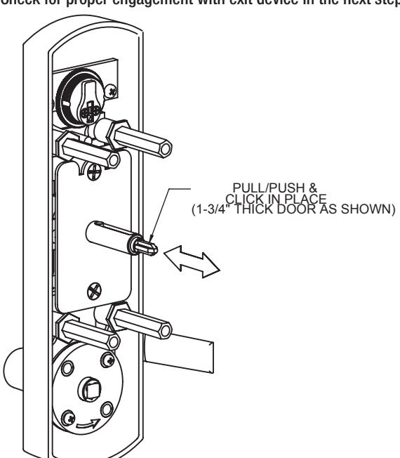
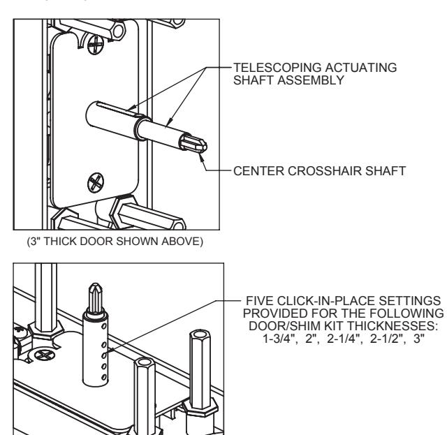
1. ADJUST TELESCOPING ACTUATING SHAFT (For BE and CE Trim only)
A. The telescoping actuating shaft assembly is preset at the factory for a 1-3/4" thick door. For thicker door applications, pull out the center crosshair shaft until it clicks into the appropriate position. There are 5 click-in-place positions: 1-3/4", 2", 2-1/4", 2-1/2", and 3". For other door/shim kit thicknesses, use the closest option.
B. Check for proper engagement with exit device in the next step.
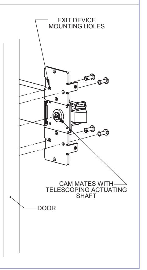
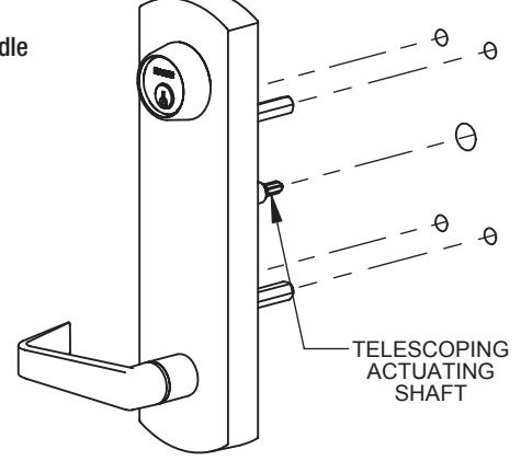
2. INSTALL ESCUTHEON TRIM
- A. Insert trim mounting posts and actuating shaft through door.
- Mate trim actuating shaft with cam on back of exit device.
- C. Secure from push side of door with provided 1-4"-20 screws.
- D. Test installation by rotating lever handle or key to verify trim.
NOTE: Dummy Trim is only for pulling door--handle does not rotate.
NOTE: 45CE CYLINDER ESCUTCHEON SHOWN ABOVE. OTHER TRIM FUNCTIONS WILL DIFFER SLIGHTLY FROM DIAGRAM.