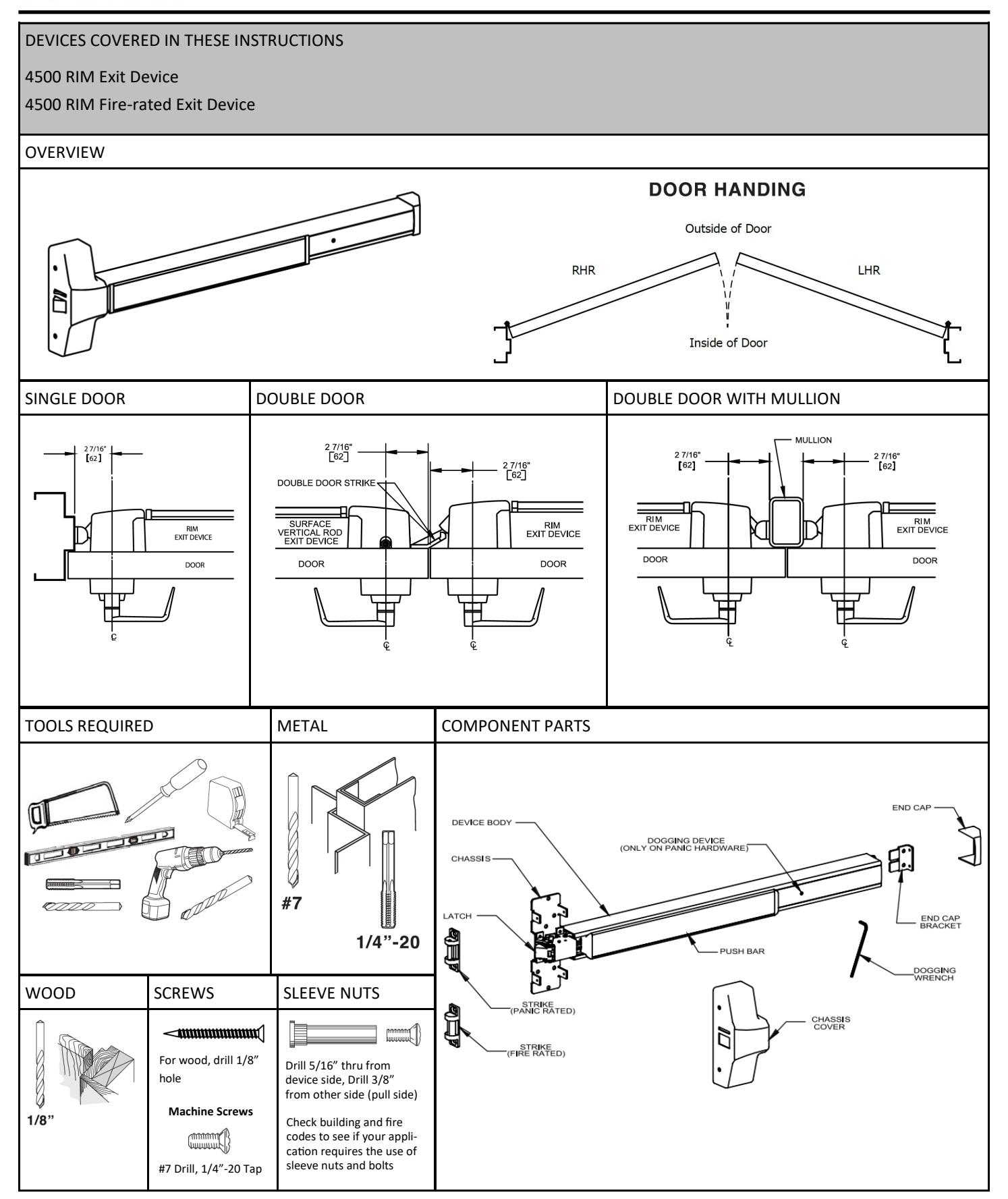
4500 Series Rim Installation Instructions – I-ED00789
Open the original PDF document
View PDF

Rev 3, Rev Date: 12/12/24 Page 1 of 3

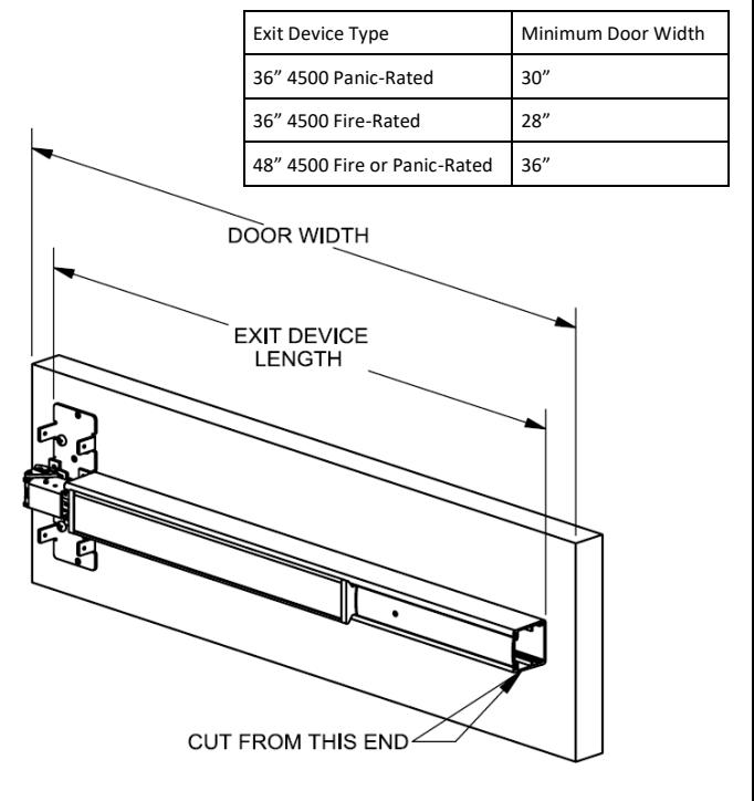
1. CUT EXIT DEVICE TO LENGTH
The exit device comes in two sizes: one sized for a 36" door width and one sized for a 48" door width. For other door widths, cut exit device to appropriate length. The recommended overall length of the exit device is equal to the door width minus four inches. Cut with hack saw or metal cutting blade. Deburr edges. Use table below to determine the minimum door width that a device can be cut down to accomodate. For electrified devices, please see the website.
2. MARK DOOR AND DRILL MOUNTING HOLES
Measure center line of exit device, typically 40" from finished floor. Fold and apply template to door and up against stop. Mark and drill holes as shown on template. Be sure the vertical line of the exit device mounting holes is 2-7/16" from the face of the stop. Do not drill center hole on strike until after strike has been mounted and adjusted.
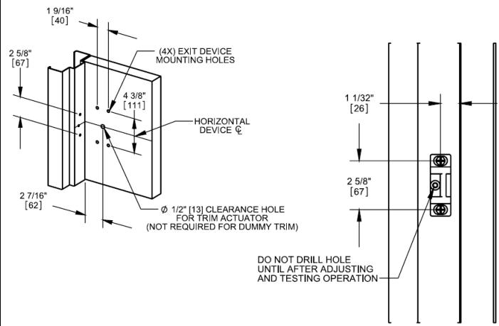
- For surface mouting on metal doors, drill and tap for 1/4"-20 machine screws for both exit device and strike.
- For surface mounting on wood doors, pre-drill 1/8" holes.
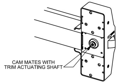
- If mounting trim, drill 5/16" clearance holes on exit device side (push side) of door and 1/2" holes on pull side. Trim requires an additional 5/8" clearance hole for the trim actuating shaft (not required for dummy trim).
- If using sleeve nuts, drill 5/16" clearance holes on exit device side (push side) of door and 3/8" holes on pull side.
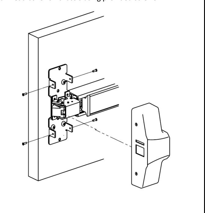
3. INSTALL DEVICE
Remove head cover from exit device chassis. Mount exit device using the 4 mounting holes indicated on template.
If using trim, be sure to line up the trim actuating shaft (tailpiece) with the cam located on back of the exit device chassis.
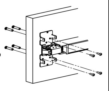
Screws:
- Metal Door surface mounting, sleeve nut or trim: 1/4" -20 machine screws (4)
- Wood Door surface mounting: #12 wood screws (4)
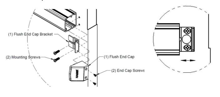
4. INSTALL END CAP
- A. Remove the flush end cap from the flush end cap bracket.
- B. Mark hole locations by holding flush end cap bracket up against door and device. Be sure exit device is level before inserting the flush end cap bracket into the device.
- C. Mark and drill/tap holes.
- D. Install flush end cap bracket and flush end cap using supplied screws. If the flush end cap is not flush with the exit device, remove flush end cap and adjust the mounting screws and the flush end cap bracket as needed.
Page 2 of 3
Rev 3, Rev Date: 12/12/24

Install strike using only the top and bottom slotted holes and 1/4"-20 machine screws (metal) or pre-drill 1/8" holes for #12 wood screw. Open and close door to verify latch and deadlatch are aligned properly. For tight fit, move strike away from door. For loose fit, move strike towards door. Once strike is adjusted, install center screw.
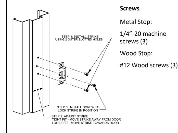
5. INSTALL STRIKE 6. INSTALL COVER
Install head cover on chassis using provided screws.
7. DOG DEVICE (Panic-rated devices only)
the latch will actuate to lock the door.
A. For increased life of the device, dog the push bar down during high traffic periods of the day.
B. Hex Wrench Dogging:
To dog the device, press the push bar, insert the hex dogging wrench and turn clockwise 35 degrees. The push bar will remain depressed and the latch will stay in the Door Open Position. (See Figure 7-1) To release the dogging, hold the push bar down, insert the hex dogging wrench and turn counter-clockwise 35 degrees. The push bar will return to the up position and
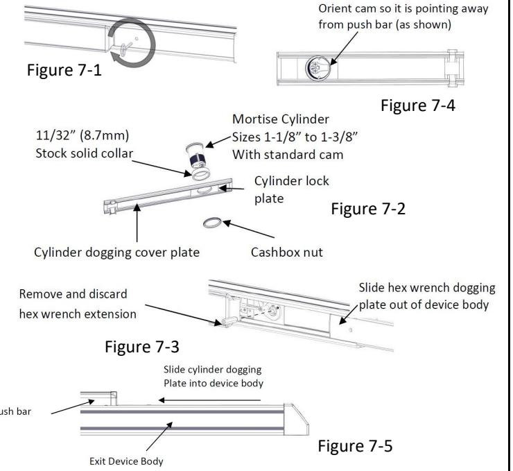
C. Cylinder Dogging:
Required hardware for cylinder dogging includes one (1) mortise cylinder, lengths 1-1/8", 1-1/4" or 1-3/8"with a standard cam (0.723" [18mm] screw center to tip of cam): and one (1) Hager Cylinder Dogging kit (4926) which includes one (1) 11/32" [8.7mm] solid cylinder collar and cashbox nut. (See Figure 7-2) Remove and discard the hex wrench extension. (See Figure 7-3) The cylinder should be oriented so the cam is pointing away from the exit device push bar. (See Figure 7-4) Install the dogging cover plate with the cylinder and test the dogging. (See Figure 7-5) Depress the push bar, insert the key and turn the key clockwise to dog the device. Turn the key counter-clockwise to release the dogging.
Rev 3, Rev Date: 12/12/24 Page 3 of 3