4500 SVR Door Prep Template – T-ED00873-Rev02
Open the original PDF document
View PDF

Rev 02, Rev Date: 07/16/2024 Page 1 of 2

4500 SURFACE VERTICAL ROD EXIT DEVICE DOOR PREP TEMPLATE T-ED00873
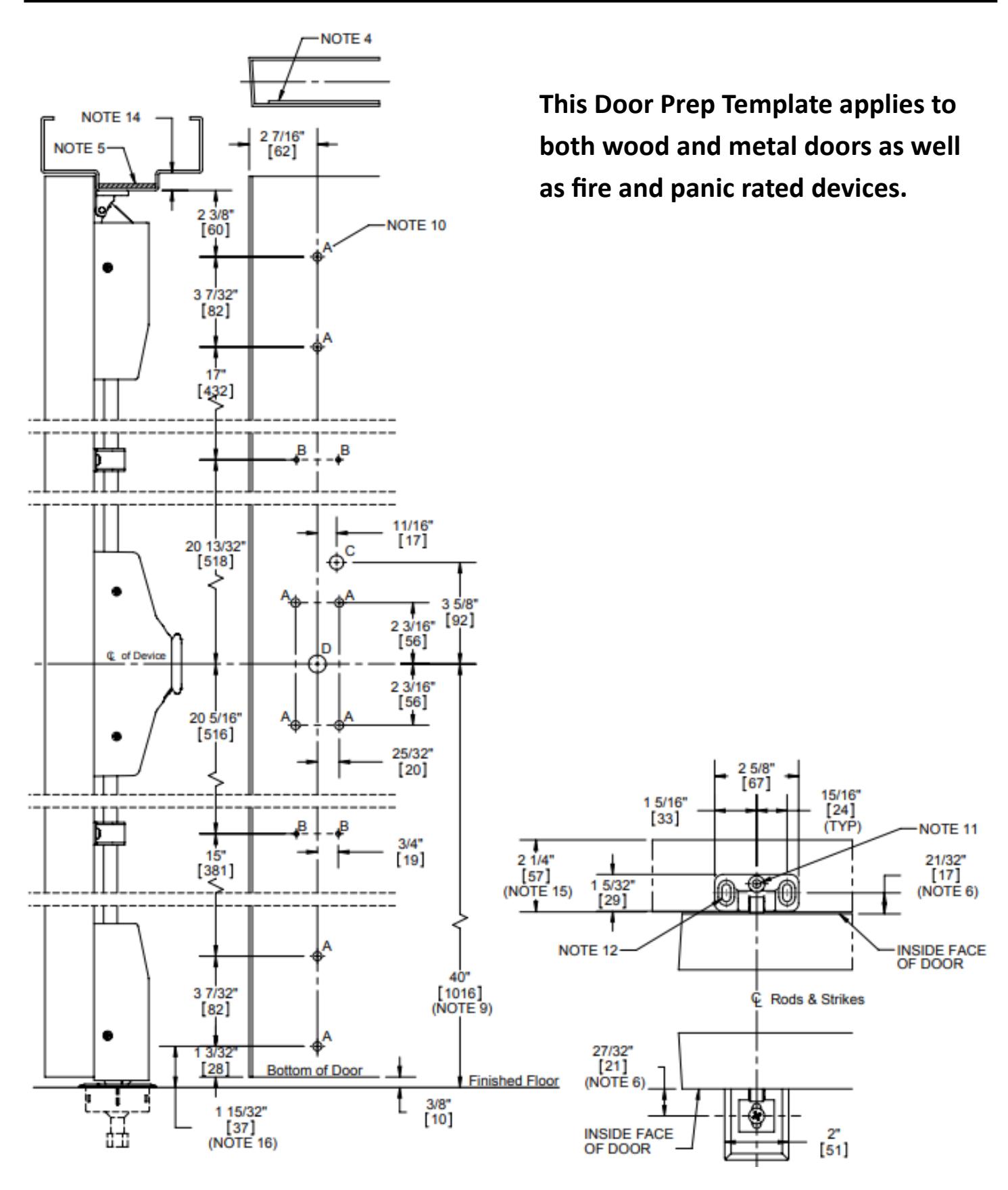
This Door Prep Template applies to applications for both wood and metal doors as well as fire and panic rated devices.
Notes:
- 1. LHR Door shown. Preparation is typical for both door hands.
-
2. Minimum Stile width:
- i. 4-7/8" for double doors.
- ii. 5-3/8" for single doors with standard 5/8" stop.
- iii. 5-3/4" for double doors with 2" mullion.
- 3. Prepare mounting holes when installing the device.
- 4. Provide door stiffeners as needed to prevent door collapse due to installation with power tools, door use, or abuse.
- 5. Provide frame stiffeners as needed for top strike. Unreinforced frames require blind rivet nuts (by others) to mount the strike.
- 6. Dimension from door face.
- 7. Device mount (end cap bracket) to hinge stile (not shown) requires hole location and preparation during device installation.
- 8. For outside trim preparation, see appropriate trim template.
- 9. Recommended height may be determined by design specs.
-
10. Screw size and installation detail (see letters "A" thru "D" on the drawing to identify the hole and hole location)
-
A. Device mounting holes (4 places)
- i. Metal door: 1/4"-20 tap (Std.)
- ii. Wood door (solid core): Pre-drill Ø 1/8" holes.
- iii. SNB: Ø 5/16" inside door face, Ø 3/8" outside door face.
- iv. Trim: Ø 5/16" inside door face, Ø 1/2" outside door face.
- v. Check building and fire codes to see if your application requires the use of SNB (sleeve nuts and bolts).
-
B. Rod guide mounting holes (4 places):
- i. Metal Door: #8-32 Tap (Std.)
- ii. Wood Door (solid core): Predrill 1/8" holes.
- C. Ø 1/2" thru-hole is required if using the electric trim (45ET).
-
D. Trim Tailpiece hole:
- i. For BE, CE, and ET trim: Ø 5/8" (thru hole)
- ii. Dummy Trim: not required
- iii. Night Latch trim: See template for details.
-
A. Device mounting holes (4 places)
- 11. This hole MUST be field located using the physical part as a template, after installation is complete and device is fully operational.
-
12. Strike mounting holes (2 places):
- i. Metal door: 1/4"-20 Tap (Std.)
- ii. Wood door: Pre-drill Ø 1/8" holes.
-
13. Reference ANSI/SDI A250.8 for door and frame clearances:
- i. Maximum of 1/8" is typical for single swing and pairs of doors.
-
ii. The meeting edges of pairs of doors:
- Standard is 3/16 ± 1/16".
- Fire-Rated pair is 1/8" ± 1/16".
- iii. Consult design specs before preparing doors.
- 14. 5/8" typical for hollow metal frames, 1/2" typical for wood frames. Consult design specs before preparing doors.
- 15. Minimum stop width is 1-3/8" for proper top strike installation.
- 16. Hole location measured from finished floor or top of threshold.
- 17. For use with astragals or meeting stiles, adjust the backset as needed.
Rev 02, Rev Date: 07/16/2024 Page 2 of 2