4500 Electrified Mortise Installation Instructions I-ED01865-rev1
Open the original PDF document
View PDF

DEVICES COVERED IN THIS DOCUMENT:
4501N EL/EU 12/24V Fail Safe/Fail Secure Electrified Mortise Exit Lock Body
Note: This document only applies to the electrifications that can be done to the Mortise Exit Device Lock Body alone. The Request to Exit (RX), Motorized Latch Retraction (MLR), Electric Dogging (ED), Delayed Egress (DE), Onboard Delayed Egress (OBDE), Alarm Kit (ALK) and Dual RX are all available modifications to the mortise exit device but are included in the push bar. For more information about those please see the electrified exit device documentation.
FUNCTION DESCRIPTION
4501N EL – Fail Safe Electrified Mortise Exit Lock Body
Outside trim is locked when power is applied and unlocked when power is removed. Trim will unlock in the event of a power failure. Key cylinder momentarily overrides locking control.
4501N-EU – Fail Secure Electrified Mortise Exit Lock Body
Outside trim is unlocked when power is applied and locked when power is removed. Trim will lock in the event of a power failure. Key cylinder momentarily overrides locking control.
ELECTRICAL SPECIFICATIONS
4501N EL/EU
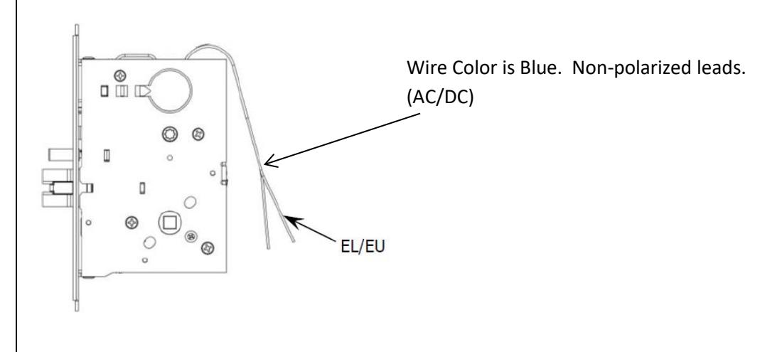
Voltage: 12-24V AC/DC (11V-30V)
Current: 250 mA MAX Inrush, 10mA MAX holding
2-Conductor Wire Run
| Distance 12V/24V | Wire Gauge |
|---|---|
| 125'/250' | 22 |
| 200'/400' | 20 |
| 300'/600' | 18 |
| 500'/1000' | 16 |
| 750'/1500' | 14 |
| 1250'/2500' | 12 |

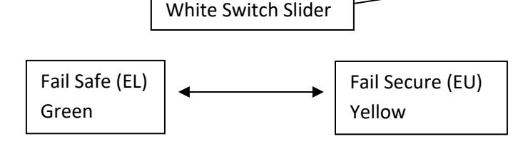
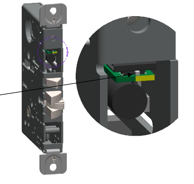
4501N EL/EU Function Change
The 4501N EL/EU is set to Fail Secure (EU) when shipped. This can be changed to EL by sliding the White switch from Yellow to Green as shown to the right. The unit must have power applied at least once beforethe lockset changes state. Note that the latch bolt may be momentarily retracted by key even if the lockset is electrically locked.
Door, Frame and Raceway Preparations
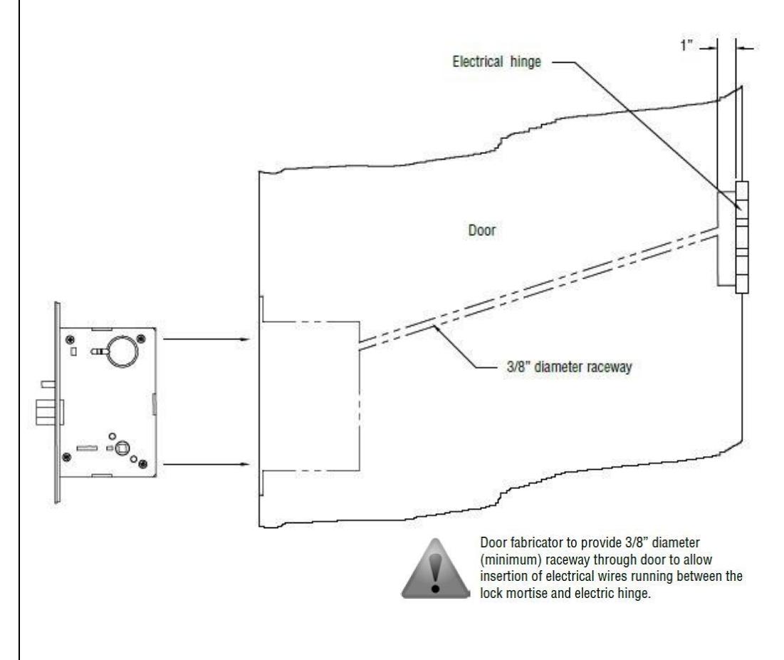
Follow mortise exit device lock body instructions and template to prepare door and frame for installation. Since the motor is located inside the lock body, there are no special preparations or alterations to the standard installation except for the raceway to route wires.
Door raceway preparations are required to route electrical wires. See diagram to the left for raceway specifications. See Mortise Exit Device Instructions (I-ED01553) and template (T-ED01545)to complete installation.