4397HP Jamb Switch Box Installation Instructions
Open the original PDF document
View PDF4397HP Jamb Switch Box INSTALLATION INSTRUCTIONS
FOR ASSISTANCE, CALL SARGENT AT 1-800-727-5477.
STEP 1
Determine switch mounting location based on mounting surface construction, applicable standards and intended use.
Step 2.
Punch out the two mounting holes in the bottom of the jamb switch box in the areas provided. Use caution not to damage any electronics present in the box. For hardwired applications, also punch out the wiring access hole.
Step 3.
Drill holes for intended fastener in mounting surface using the mounting box as your template. In hardwired installations, drill a wiring access hole.
Step 4.
Insert the appropriate fastener through the box and into the mounting surface and tighten securely.
Step 5.
In hardwired installations, wire the jamb switch to the door controller using the NO and COMMON contacts. For radio-controlled installations, wire the jamb switch to the transmitter using the NO and COMMON contacts.
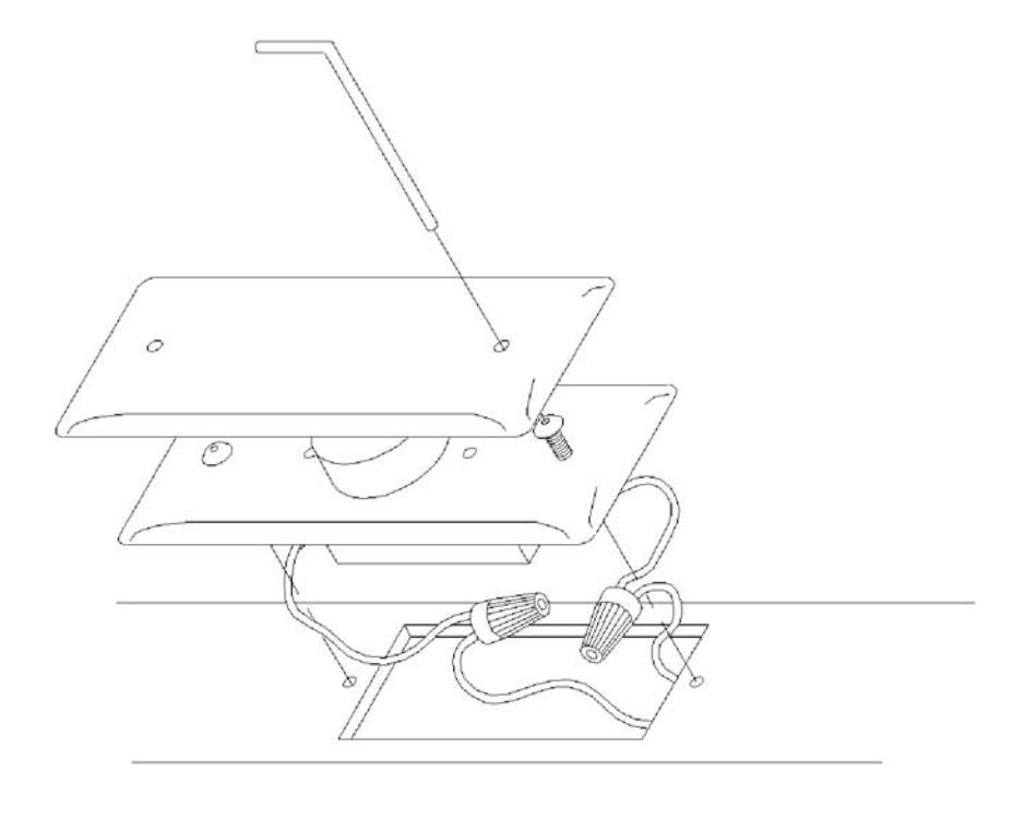
Step 6.
Use the enclosed wrench to tighten the #6-32 screws into the jamb box (as shown above-right).
Step 7.
Test for activation.
Observe all manufacturers recommendations for safety and operation of their products. ANSI/BHMA standards that offer specific recommendations for each type and class of automatic door have been developed. To obtain a copy of the ANSI/BHMA standard that applies to your installation, visit www.buildershardware.com or www.ansi.org.
4397HP Jamb Switch INSTALLATION INSTRUCTIONS
FOR ASSISTANCE, CALL SARGENT AT 1-800-727-5477.
STEP 1.
Determine switch mounting height based on applicable standards and intended use.
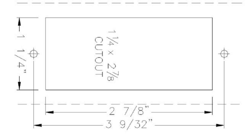
Step 2.
Use the template provided to mark the clearance and mounting holes for the jamb switch. Cut out the opening and drill and tap for #6-32 machine screws
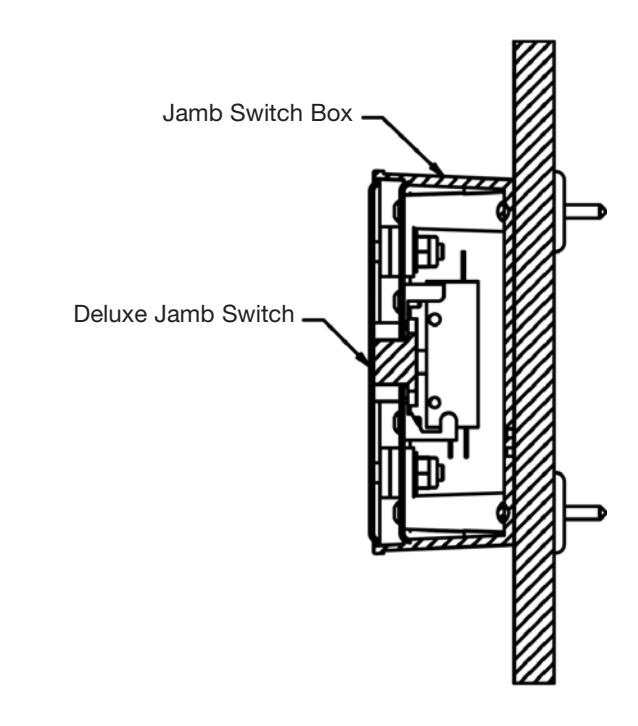
Step 3.
Wire the jamb switch to the door control using the NO and COMMON contacts and test for activation.
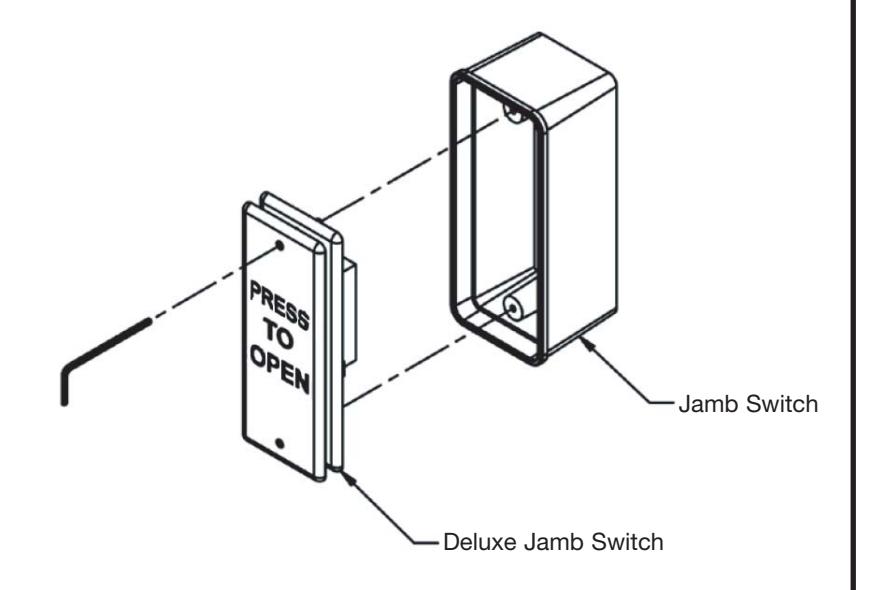
Step 4.
Tighten screws through holes in cover plate with hex key provided