4390 Series Wall Switches (Press Plates) Installation Instructions
Open the original PDF document
View PDF4390 SERIES WALL SWITCH INSTALLATION
FOR ASSISTANCE, CALL SARGENT AT 1-800-810-WIRE.
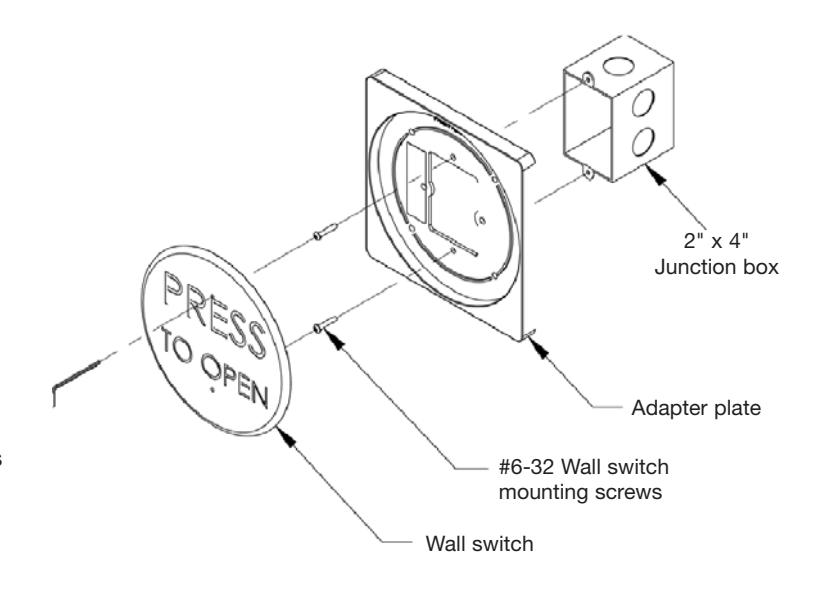
2" x 4" (Single Gang) Wall Switch Mounting
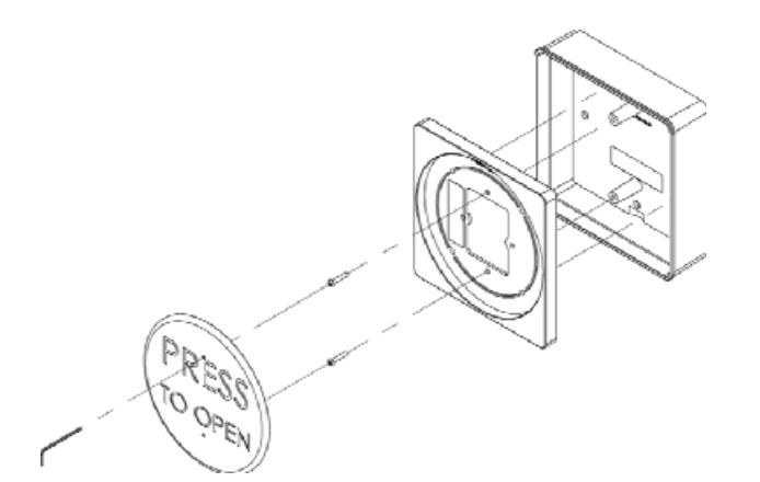
Step 1: Install a 2" x 4" (single gang) mounting box in the area in which the wall switch is to be installed. Be sure the screws are vertically orientated and ensure there is adequate clearance on each side to accommodate the adapter plate.
Step 2: Wire the wall switch to the door controller using the Normal Open and Common contacts (See drawing on reverse side).
Step 3: Thread the enclosed #6-32 screws through the adapter plate and into the 2" x 4" junction box, tightening until approximately 1/4" remains visible.
Step 4: Slide the back plate of the switch over the screws and allow it to settle. Use the enclosed wrench to tighten and secure wall switch plate.
Step 5: Test for activation.
4" x 4" (Double Gang) Wall Switch Mounting*
Step 1: Install a 4" x 4" (double gang) mounting box in the area in which the wall switch is to be installed. Be sure there is adequate clearance on each side to accommodate the adapter plate.
Step 2: Wire the wall switch to the door controller using the Normal Open and Common contacts (See drawing on reverse side).
Step 3: Press the #6-32 screw inserts into the holes in the seal plate as shown with the hex head flush to the face of the seal plate on the side facing the wall switch.
Step 4: Thread the enclosed #6-32 screws into the adapter plate, tightening until approximately 1/4" of the threads remain visible.
Step 5: Thread the 4" x 4" mounting box screws through the seal plate adapter and into the 4" x 4" junction box as shown. Tighten.
Step 6: Slide the back plate of the switch over the #6-32 screws and allow it to settle. Use the enclosed wrench to tighten and secure wall switch plate.
Step 7: Test for activation.
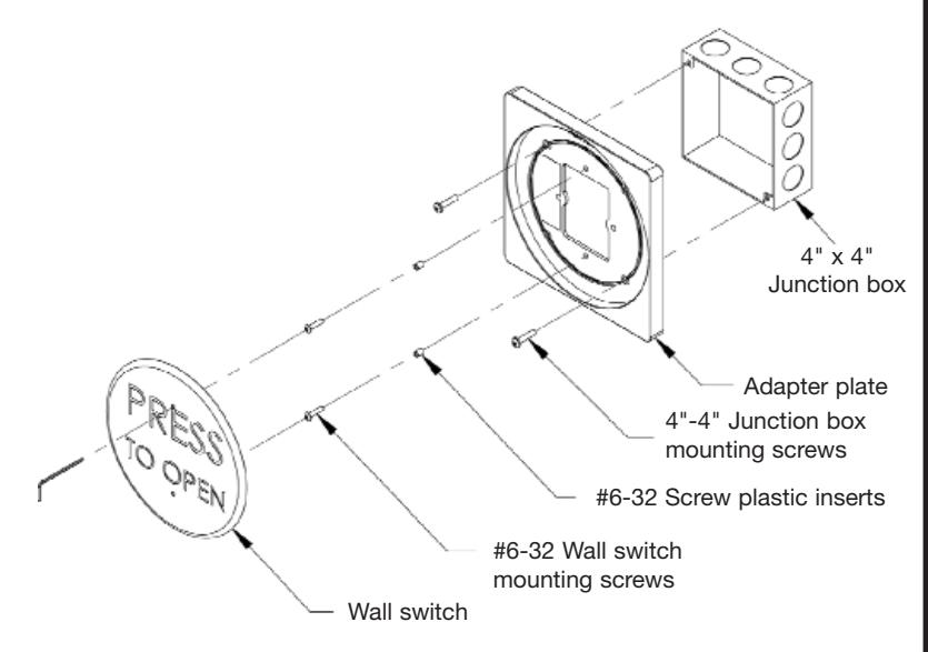
* 4-1/2& quot; Round Wall Switches cannot be mounted on 4" x 4" boxes without a special adapter plate (P/N 0022006900) available separately. Please contact factory for details.
4390 SERIES WALL SWITCH INSTALLATION
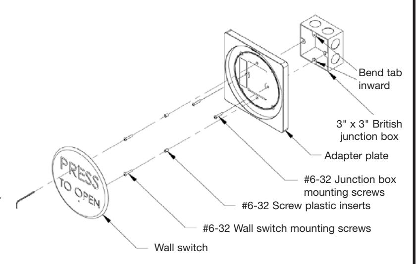
3" x 3" Box Mounting
Step 1: Install a 3" x 3" mounting box in the area in which the wall switch is to be installed. Bend upper and lower tabs inward to accommodate wall switch. Be sure there is adequate clearance on each side to accommodate the adapter plate.
Step 2: Wire the wall switch to the door controller using the Normal Open and Common contacts (See drawing below).
Step 3: Press the #6-32 screw inserts into the holes in the adapter plate as shown with the hex head flush to the face of the adapter plate on the side facing the wall switch.
Step 4: Thread the enclosed #6-32 screws into the adapter plate, tightening until approximately 1/4" of the threads remain visible.
Step 5: Thread the 3" x 3" mounting box screws into the 3" x 3" junction box and tighten.
Step 6: Slide the back plate of the switch over the #6-32 wall switch screws and allow it to settle. Use the enclosed wrench to tighten and secure wall switch plate.
Step 7: Test for activation.
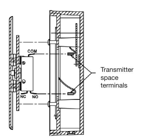
Wall Switch Wire Connection Illustration Drawing
In addition to the mounting options on this sheet, SARGENT wall switches can be mounted in any of our specially designed wall switch mounting boxes, like the universal box shown at right. Use the guidelines included with each box for proper installation.
Cleaning Wall Switches
Wall switch cover plates are manufactured from high quality stainless steel and painted with scuff-resistant coatings. To clean the cover plates, use a damp non-abrasive cloth. Regular cleaning with harsh solvents or abrasive materials may cause deterioration of the painted engraving
Observe all manufacturers' recommendations for safety and operation of their products. ANSI/BHMA standards that offer specific recommendations for each type and class of automatic door have been developed. To obtain a copy of the ANSI/BHMA standard that applies to your installation, visit www.buildershardware.com or www.ansi.org.