3800 Series Small Case Deadlock Installation Instruction I-LS01643
Open the original PDF document
View PDF

3800 Series Small Case Mortise Deadlock Installation Instructions I-LS01643
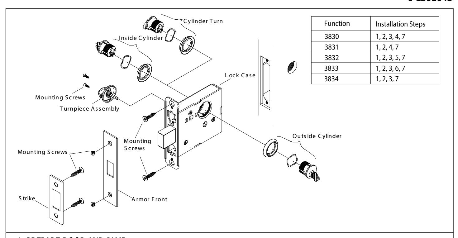
1. PREPARE DOOR AND JAMB
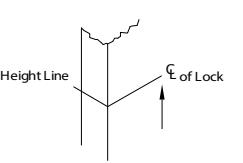
A. Mark lockset centerline.
- 1. Measure desired height from finished floor.
- 2. Mark centerline on both faces and edge of door.
CAUTION: The outside and inside of the door may require different preparation. Use proper template for outside (exterior or corridor) and inside of door.

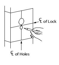
- 1. Align centerline of door template with centerline mark on door edge.
- 2. Based on the function of the lock, mark position of drill points.
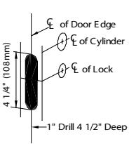
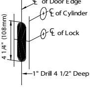
C. Mortise door edge for wood doors.
- 1. Align template with centerline of door edge.
- 2. Mark and drill two (2) 1" diameter holes, 4-1/2" deep.
- 3. Remove remaining wood until the mortise is 1" wide by 4-1/4" high by 4-1/2" deep.

Note: To precent splintering or damaging of doors, drill through holes halfway from each side of the door.

The standard recess is 1-1/4" x 5-19/32" x 7/32".
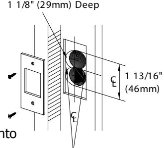
F. Install strike.
- 1. Align centerline of strike template with the centerline marked on doorjamb.
- 2. Bore 1" diameter holes into doorjamb, 1-1/8" deep.
- 3. Recess 5/32" for a flush fit of the strike box. (Additional recess is required when using strike reinforcement).
- 4. Using a Philips screwdriver and two (2) strike mounting screws, install strike into doorjamb.
7/32" (6.0mm)
1" (25mm) Holes
Clear Out for S trike B ox