3800 Series Sectional Installation Instruction I-LS00761
Open the original PDF document
View PDF

DEVICES COVERED IN THIS DOCUMENT:
3800 Series Mortise Lock - Sectional Model
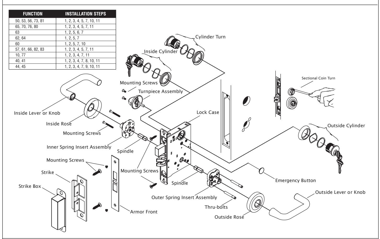
OVERVIEW
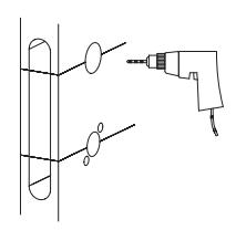
STEP 1: PREPARE DOOR AND JAMB
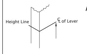
A. Mark lockset centerline of lever.
Measure desired height from finished floor.
ii. Mark centerline on both faces and edge of door.
NOTE: If mortise for strike has already been made, measure 1-7/8" down from center of strike to locate center line of lever.
CAUTION: The outside and inside of door may require different preparation. Use proper template for outside (exterior or corridor) and inside of door.
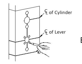
Mark trim drill points.
. Align centerline of door template with centerline marked on door edge.
ii. Based on the function of the lock, mark position of drill points.
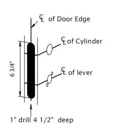
C. Mortise door edge (for wood doors).
Align template with centerline of door edge.
ii. Mark and drill two (2) 1" diameter holes, 4-1/2" deep.
iii. Remove remaining wood until the mortise is 1" wide, by 6-3/4" high, by 4-1/2" deep.
REV 3

STEP 1: PREPARE DOOR AND JAMB (cont)
D. Drill trim holes.
NOTE: To prevent splintering or damaging doors, drill through-holes halfway from each side of door.
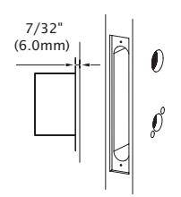
E. Create a recess for the lock face. The standard recess is 1-1/4" x 8" x 7/32".
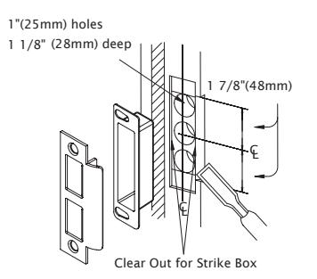
F. Install strike.
- i. Align centerline of strike template with the centerline marked on doorjamb. Be sure to match centerline on both strike and lock trim templates.
- ii. Bore 1" diameter holes into doorjamb, 1-1/8" deep.
- iii. Create a recess 5/32" deep for installation of the strike and dust box.
NOTE: Additional recess is required when using strike reinforcement.
iv. Using a Phillips screwdriver and two (2) strike mounting screws, install strike into doorjamb.
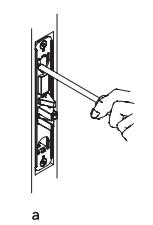
STEP 2: INSTALL LOCK CASE
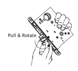
- A. Change latch handing.
- i. Pull anti-friction tongue and latchbolt away from lock case.
- ii. Rotate latchbolt 180 degrees.
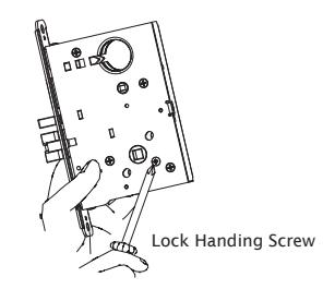
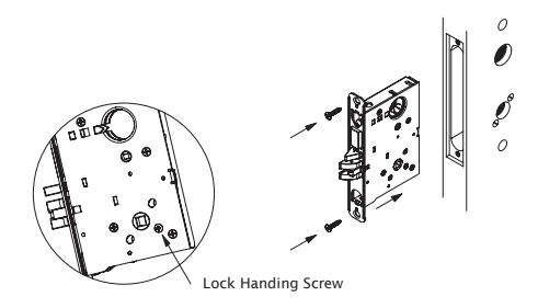
SKIP STEP "B" FOR THE FOLLOWING FUNCTIONS: 10, 17, 27, 57, 60, 62, 63, 64, 65, 66, 73, 75, 77, 80, 81, 82, 83. LOCK HANDING SCREW IS NOT REQUIRED FOR THESE FUNCTIONS.
- B. Change lock handing screw.
- i. Remove lock handing screw from side of lock case.
- ii. Install lock handing screw on other side of lock case.
NOTE: The lock handing screw must always be on the inside of the door for proper operation of the lock.
- C. Install lock case.
- i. Install with the lock handing screw on the inside of the door and leave the mounting screws slightly loose to allow for adjustment.
REV 3 Page 2 of 4

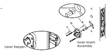
STEP 3: INSTALL OUTER INSERT ASSEMBLY
SKIP STEP "A" FOR THE FOLLOWING FUNCTIONS: 80, 81, 82, 83. SLOTTED SPINDLE IS NOT REQUIRED FOR THESE FUNCTIONS.
- A. Insert outer spindle into lock hub (short end of slotted spindle must be placed toward lock case).
- B. With lever keeper toward door edge, place insert assembly over spindle.
- C. Insert thru-bolts into appropriate holes in insert according to handing of door.
- D. Place rose over insert.
STEP 4: INSTALL INNER INSERT ASSEMBLY
- A. Insert inner spindle into lock hub (short end of slotted spindle must be placed toward lock case).
- B. With keeper pointing toward door edge, place insert assembly over spindle.
- C. Put screws through insert and thread into thru-bolts slightly loose to allow for adjustment.
Door Edge Lever Keeper
Outer Insert
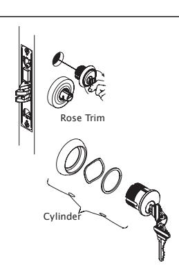
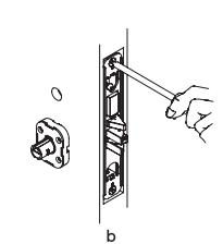
STEP 5: INSTALL CYLINDER
- A. Install cylinder if required.
- B. Loosen cylinder retaining screw sufficiently to allow cylinder to be threaded into lock case. Keyway must end up on bottom of cylinder housing.
- C. Secure cylinder by tightening retaining screw into groove on side of cylinder.
NOTE: For double cylinder, same as above.
CAUTION: If first cylinder is installed too far into case, second cylinder cannot be properly installed.
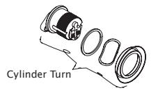
STEP 6: INSTALL CYLINDER TURN
- A. Assemble cylinder turn.
- B. Screw cylinder turn into lock case.
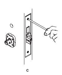
STEP 7: INSTALL ARMOR FRONT
- A. Secure cylinder by tightening cylinder anchor screw until hand-tight.
- B. Tighten two (2) lock case mounting screws.
- C. Place armor front in position and install two (2) screws.
REV 3 Page 3 of 4

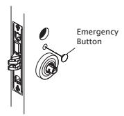
STEP 8: INSTALL EMERGENCY BUTTON
A. Snap emergency button into place.
STEP 9: INSTALL COIN TURN
A. Insert coin turn in the vertical position.
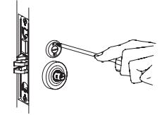
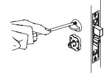
STEP 10: INSTALL THUMBTURN
- A. Insert the thumbturn in the vertical position.
- B. Throw deadbolt.
- C. Insert two (2) thumbturn mounting screws.
STEP 11: INSTALL ROSE TRIM
OUTSIDE LEVER DOES NOT CONTAIN A KEEPER RELEASE HOLE. ONLY INSIDE LEVER CONTAINS A KEEPER RELEASE HOLE.
- A. Check function and adjust assemblies if necessary.
- B. Tighten mounting screws in insert assembly.
- C. Locate the notch of rose toward bottom and push in until flush with face of door.
- D. Align outside and inside levers with sleeve and push until lever keeper engages with hole.
Note: Outside lever with no keeper hole. Only inside lever with keeper hole.
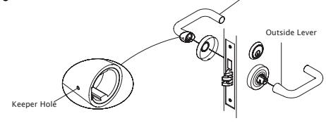
Inside Lever
REV 3 Page 4 of 4