3800 Series Escutcheon Installation Instruction I-LS00125
Open the original PDF document
View PDF

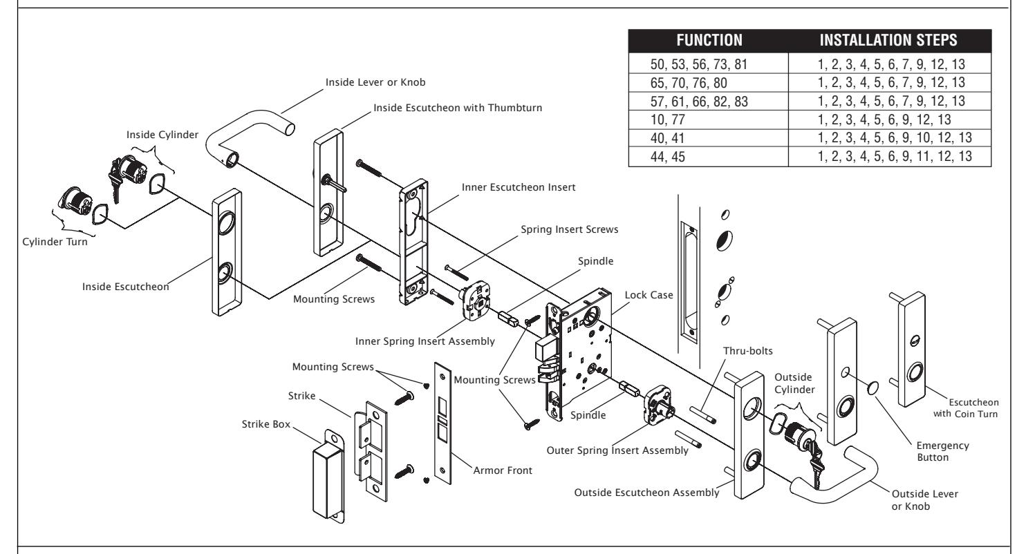
DEVICES COVERED IN THIS DOCUMENT:
3800 Series Mortise Lock - Escutcheon Model
OVERVIEW
STEP 1: PREPARE DOOR AND JAMB
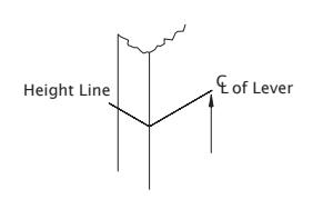
A. Mark lockset centerline of lever.
- i. Measure desired height from finished floor.
- ii. Mark centerline on both faces and edge of door.
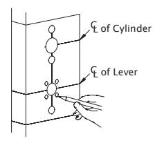
NOTE: If mortise for strike has already been made, measure 1-7/8" down from center of strike to locate center line of lever.
CAUTION: The outside and inside of door may require different preparation. Use proper template for outside (exterior or corridor) and inside of door.
B. Mark trim drill points.
- i. Align centerline of door template with centerline marked on door edge.
- ii. Based on the function of the lock, mark position of drill points.
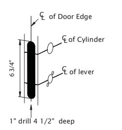
C. Mortise door edge (for wood doors).
- i. Align template with centerline of door edge.
- ii. Mark and drill two (2) 1" diameter holes, 4-1/2" deep.
- iii. Remove remaining wood until the mortise is 1" wide, by 6-3/4" high, by 4-1/2" deep.
REV 2 Page 1 of 4

STEP 1: PREPARE DOOR AND JAMB (cont)
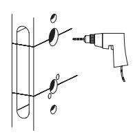
D. Drill trim holes.
NOTE: To prevent splintering or damaging doors, drill through-holes halfway from each side of door.
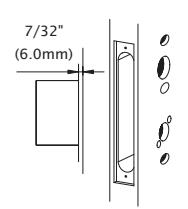
E. Create a recess for the lock face. The standard recess is 1-1/4" x 8" x 7/32".
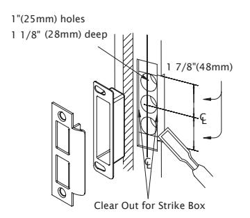
F. Install strike.
- i. Align centerline of strike template with the centerline marked on doorjamb. Be sure to match centerline on both strike and lock trim templates.
- ii. Bore 1" diameter holes into doorjamb, 1-1/8" deep.
- iii. Create a recess 5/32" deep for installation of the strike and dust box.
NOTE: Additional recess is required when using strike reinforcement.
iv. Using a Phillips screwdriver and two (2) strike mounting screws, install strike into doorjamb.
STEP 2: INSTALL LOCK CASE
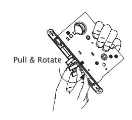
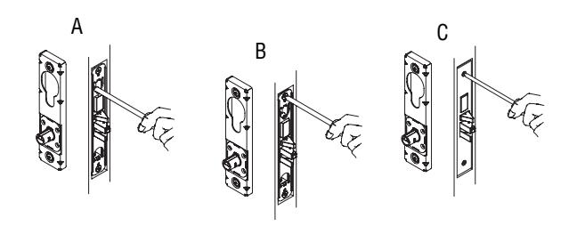
- A. Change latch handing.
- i. Pull anti-friction tongue and latchbolt away from lock case.
- ii. Rotate latchbolt 180 degrees.
SKIP STEP "B" FOR THE FOLLOWING FUNCTIONS: 10, 17, 27, 57, 65, 66, 73, 75, 77, 80, 81, 82, 83. LOCK HANDING SCREW IS NOT REQUIRED FOR THESE FUNCTIONS.
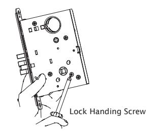
- B. Change lock handing screw.
- i. Remove lock handing screw from side of lock case.
- ii. Install lock handing screw on other side of lock case.
NOTE: The lock handing screw must always be on the inside of the door for proper operation of the lock.
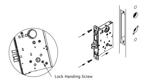
- C. Install lock case.
- i. Install with the lock handing screw on the inside of the door and leave the mounting screws slightly loose to allow for adjustment.

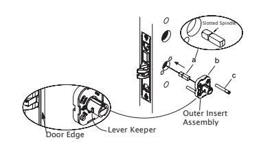
STEP 3: INSTALL OUTER INSERT ASSEMBLY
SKIP STEP "A" FOR THE FOLLOWING FUNCTIONS: 80, 81, 82, 83. SLOTTED SPINDLE IS NOT REQUIRED FOR THESE FUNCTIONS.
- A. Insert outer spindle into lock hub (short end of slotted spindle must be placed toward lock case).
- B. With lever keeper toward door edge, place insert assembly over spindle.
- C. Insert thru-bolts into appropriate holes in insert according to handing of door.
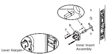
STEP 4: INSTALL INNER INSERT ASSEMBLY
- A. Insert inner spindle into lock hub (short end of slotted spindle must be placed toward lock case).
- B. With keeper pointing toward door edge, place insert assembly over spindle.
- C. Put screws through insert and thread into thru-bolts slightly loose to allow for adjustment.
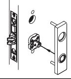
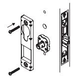
STEP 5: INSTALL OUTSIDE ESCUTCHEON ASSEMBLY
INSTALL A CONCEALED CYLINDER BEFORE INSTALLING OUTSIDE ESCUTCHEON.
A. Place outside escutcheon assembly over spring insert assembly and align with door.
STEP 6: INSTALL INNER ESCUTCHEON INSERT
A. Place escutcheon insert over spring insert. Install screws through insert and thread into posts of outside escutcheon slightly loose to allow for adjustment.
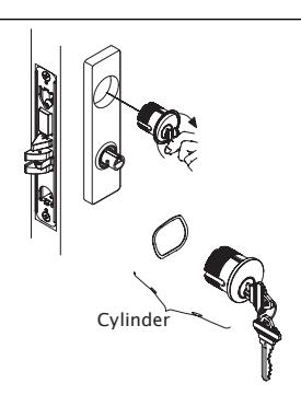
STEP 7: INSTALL CYLINDER
- A. Install cylinder if required.
- B. Loosen cylinder retaining screw sufficiently to allow cylinder to be threaded into lock case. Keyway must end up on bottom of cylinder housing.
- C. Secure cylinder by tightening retaining screw into groove on side of cylinder.
NOTE: For double cylinder, same as above.
CAUTION: If first cylinder is installed too far into case, second cylinder cannot be properly installed.
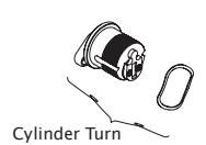
STEP 8: INSTALL CYLINDER TURN
- A. Assemble cylinder turn.
- B. Screw cylinder turn into lock case.
REV 2 Page 3 of 4

STEP 9: INSTALL ARMOR FRONT
- A. Secure cylinder by tightening cylinder anchor screw until hand-tight.
- B. Tighten two (2) lock case mounting screws.
- C. Place armor front in position and install two (2) screws.
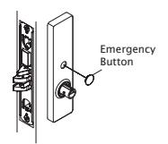
STEP 10: INSTALL EMERGENCY BUTTON
A. Snap emergency button into place.
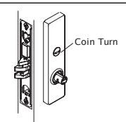
STEP 11: INSTALL COIN TURN
A. Insert coin turn in the vertical position.
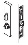
STEP 12: INSTALL INSIDE ESCUTCHEON ASSEMBLY
- A. Check function and adjust assemblies if necessary.
- B. Tighten mounting screws in inner spring insert and escutcheon insert.
- C. Place thumbturn in vertical position and push escutcheon flush with face of door.
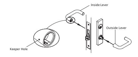
STEP 13: INSTALL INSIDE LEVER AND OUTSIDE LEVER
OUTSIDE LEVER DOES NOT CONTAIN A KEEPER RELEASE HOLE. ONLY INSIDE LEVER CONTAINS A KEEPER RELEASE HOLE.
A. Align outside and inside levers with sleeve and push until know keeper engages with hole.
Note: Outside lever with no keeper hole. Only inside lever with keeper hole.
REV 2 Page 4 of 4