3700 Series Installation Instruction I-LS00770
Open the original PDF document
View PDF

3700 Series ANSI Grade 2 Interconnected Lock
Installation Instructions Meets ANSI 156.12 I-LS00770
For use on doors 1-3/8" to 2" (35 mm - 51 mm) thick
1. MARK DOOR
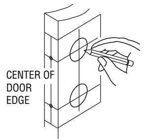
Place template on high edge of door bevel, suggested height 38" (965 mm) from floor. On door edge, mark centers of 1" (25.4 mm) holes for both top latch and bottom latch. Check backset of the lock you are installing, either 2-3/8" or 2-3/4" (60 mm or 70 mm). On door face, mark centers of 2-1/8" (54 mm) holes for top and deadbolt bottom leverset. NOTE: Be sure to use correct backset size.
2. DRILL HOLES
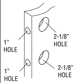
Drill 2-1/8" (54 mm) hole for top deadbolt and 2-1/8" (54 mm) hole for bottom leverset through door face. Drill holes from both sides of door face to prevent splitting. Drill two 1" (25.4 mm) holes through centers of door edge.
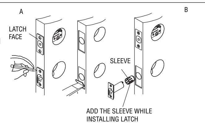
3. INSTALL LATCHES
- A. Insert latch in holes. Latch faces must be parallel to door face. Mark latch face outline on door edge and remove latches. Chisel 5/32" (4 mm) deep or until latch faces are flush with door edge. Insert latches and tighten #8 screws securely.
- B. Latch faces should be vertically aligned.
- C. Face plate will be flush with door edge after tightening the screws.
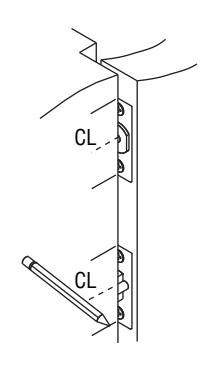
4. INSTALL STRIKES
- A. Close door until latchbolts touch jamb to locate strike on jamb and center line of strike. Open door and extend line from mark to door stop. Measure one half of door thickness plus 1/8" (3.2 mm) from stop and vertically mark center line for strike.
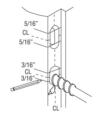
- B To prep the deadbolt strike, drill two (2) 1" (25.4 mm) diameter holes 1" deep in door jamb 5/16" (8 mm) above and 5/16" (8 mm) below the horizontal center line. To prep the T-strike, drill two (2) 1" (25.4 mm) diameter holes 5/8" (15.9 mm) deep in door jamb 3/16" (4.7 mm) above and 3/16" (4.7 mm) below the horizontal center line.
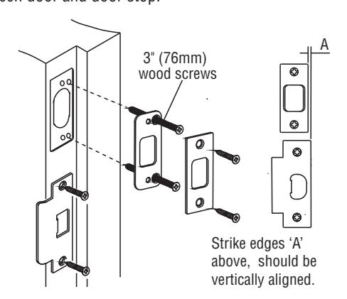
- C. Match screw holes on the deadbolt strike with vertical center line on jamb. Mark the outline of the strike and chisel that area 1/4" (6.4 mm) deep for flush fit of dust box, wood frame reinforcer, and strike. Tighten dust box and wood frame reinforcer to frame using 3" wood screws. Insert strike and tighten to frame using #8 screws. Next, mark outline of T-strike on jamb. Mortise that area 3/32" (2.4 mm). Tighten T-strike to the frame using two (2) #8 screws. NOTE: Bottom strike has an adjustable tab that can be bent in or out to eliminate loose fit between door and door stop.
REV 2 Page 1 of 3

3700 Series ANSI Grade 2 Interconnected Lock

Installation Instructions Meets ANSI 156.12 I-LS00770
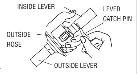
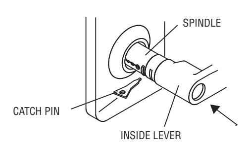
5. REMOVE INSIDE LEVER
Use lever catch pin to depress lever catch visible under inside sleeve collar and slide lever off spindle.
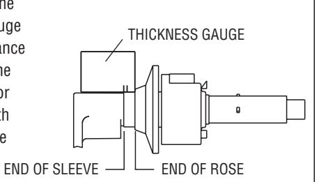
6. ADJUST DOOR THICKNESS
Adjust for door thickness by using the provided scale gauge. The scale gauge should be used to measure the distance between the end of the sleeve and the end of the rose. Rotate the rose in or out to align the end of the sleeve with the tick mark that corresponds to the proper door thickness.
7. INSTALL LOCK ASSEMBLY
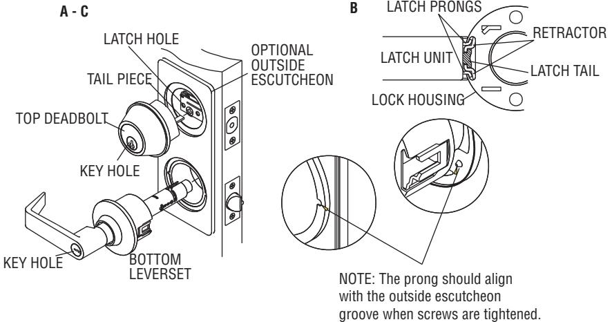
- A. Place optional outside escutcheon on exterior door face.
- B. Insert leverset into bottom latch. Latch must be in place before installing lock. Be sure to have lock housing engaged with latch prongs and retractor engaged with latch tail. CAUTION: Do not attempt to install lock with door closed.
WARNING: To ensure correct connection between deadbolt and cylindrical lock, make sure that the latchbolt of the upper deadbolt is not projecting prior to inserting the tail piece into the latch hole horizontally.
C. Install deadbolt exterior keyed cylinder and guard. Be sure to insert tail piece horizontally through latch hole.
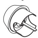

TAIL PIECE LATCH HOLE

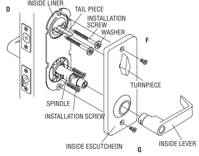
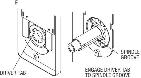
- E. Slide inside escutcheon onto spindle of bottom lock so driver tab engages with spindle groove. Change direction of driver tab from left to right or right to left if necessary to achieve proper door handing (see step 8 for detail).
- F. Slide tail piece of deadbolt onto turnpiece groove.
- G. Tighten two screws on inside escutcheon securely.
REV 2 Page 2 of 3

3700 Series ANSI Grade 2 Interconnected Lock

Installation Instructions Meets ANSI 156.12 I-LS00770
8. INSTALL INSIDE LEVER
H. Install inside lever, use pin to press down the lever catch in the hole and push inside lever all the way in until catch clicks into catch hole.
I. Properly installed, the latchbolt will retract by rotating the lever in the downward direction only.
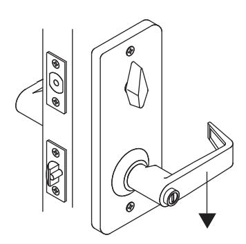
See illustration shown below to determine hand of door.
CHANGE HAND OF DRIVER TAB
There are two driver tabs, one at the left side and one at the right side. Sliding driver tab to right side (or left side) will automatically pull out driver tab at left side (or right side). Use correct driver tab to match handing of door.
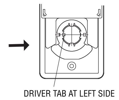


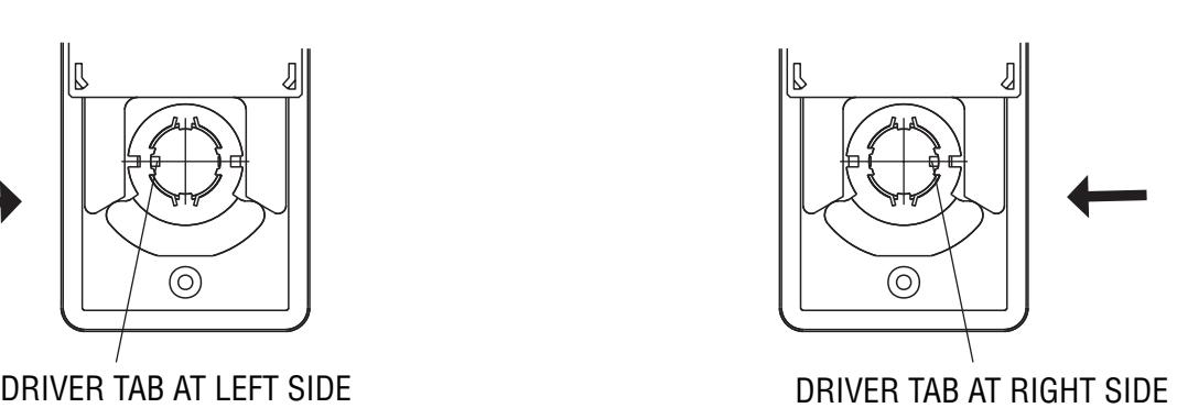
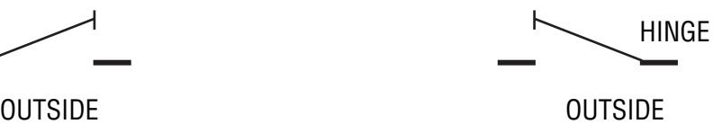
LEFT HANDED DOOR RIGHT HANDED DOOR
REV 2 Page 3 of 3