3600 Series Installation Instruction – I-LS00769
Open the original PDF document
View PDF

3600 Series ANSI Grade 2 Tubular Lever Set Installation Instructions Meets ANSI 156.2 I-LS00769
For use on doors 1-3/8" to 1-3/4" (35 mm - 45 mm) thick TOOLS REQUIRED FOR NEW INSTALLATION: (1) Phillips Head Screwdriver (1) 2-1/8" (54 mm) Hole Saw (1) 1" (25.4 mm) Drill Bit (1) Chisel TOOLS REQUIRED FOR REPLACEMENT INSTALLATION: (1) Phillips Head Screwdriver FOR REMODELING OR NEW CONSTRUCTION: -Follow all steps FOR REPLACEMENT OF EXISTING LOCK: -Follow steps 1, 3C, 4C, 5C, 6 through 9 after removal of old lock FOR CYLINDER REPLACEMENT: -Follow Step 10 OUTSIDE ROSE ASSEMBLY OUTSIDE LEVER (REVERSIBLE) SPINDLE SCREW POST OUTSIDE FIRE SHIELD LATCH SCREWS ASA STRIKE FACE PLATE LATCH INSIDE FIRE SHIELD INSIDE MOUNTING ASSEMBLY MOUNTING SCREWS INSIDE ROSE TURN PIECE INSIDE LEVER (REVERSIBLE) (ILLUSTRATION: ENTRANCE FUNCTION)
1. LATCH BACKSET ADJUSTMENT
A. If 2-3/4" backset is required, pull spindle cam all the way to the right edge of the adjusting hole.
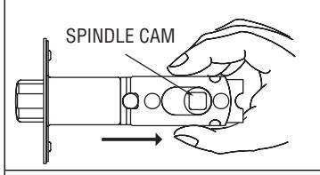
B Be sure spindle hole is properly aligned. It is important that the spindle hole remains properly aligned throughout the installation.


RIGHT WRONG
C. The latch is now set for 2-3/4" backset.
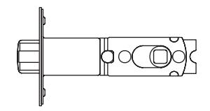
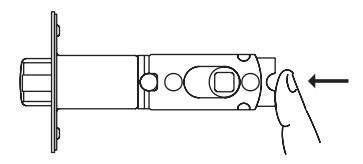
D. To reset the latch to 2-3/8" backset, push the spindle cam to the left edge of the adjusting hole.
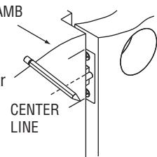
2. MARK DOOR
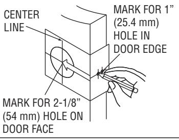
Measure center line of lock; height as desired from finished floor. Select 2-3/8" or 2-3/4" backset, fold and apply template to high side of door bevel and mark center of door edge as indicated on template. Mark center hole on door face through guide on template.
3. DRILL HOLES
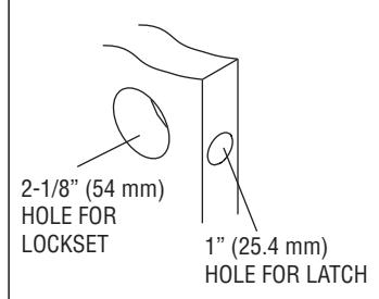
Drill 2-1/8" (54 mm) hole through door face as marked for lockset. (It is recommended that holes be drilled from both sides on wood doors to prevent splitting.) Drill 1" (25.4 mm) hole in center of door edge for latch.
4. INSTALL LATCH
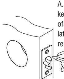
A. Insert latch in hole keeping it parallel to face of door. Mark outline of latch face plate and remove latch.
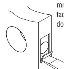
B. Chisel 5/32" (4 mm) deep or until latch face plate is flush with door edge.
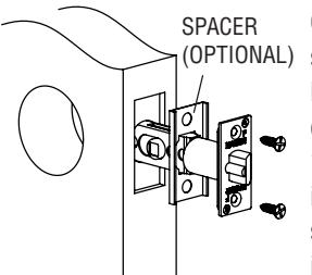
C. Insert latch and tighten screws. NOTE: Latchbolt bevel must face to closing direction. For doors with a 1-1/8" wide latch cutout, insert latch through optional spacer and then install latch in door.
REV 2 Page 1 of 2

3600 Series ANSI Grade 2 Tubular Lever Set Installation Instructions
Meets ANSI 156.2 I-LS00769
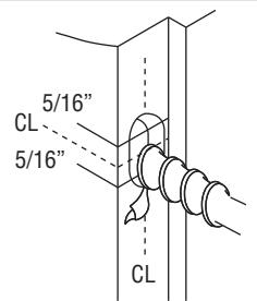
5. INSTALL STRIKE
A. Close door until latchbolt touches jamb. Locate strike in jamb and center line of strike. Open door and extend line to door stop. Measure one half of door thickness plus 1/8" from door stop. Vertically mark center line for strike. JAMB
B. Drill two (2) 1-inch (25.4 mm) holes 3/4" (19 mm) deep in door jamb 5/16" (8 mm) above and 5/16" (8 mm) below horizontal center line. CAUTION: To ensure poper lockset function, hole in jamb must be drilled a full 3/4" (19 mm) deep.
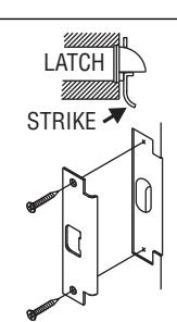
C. Cut out jamb mortise for strike 3/32" (2.4 mm) deep or until strike is flush with jamb. Tighten screws. Latch stops against strike, as illustrated.
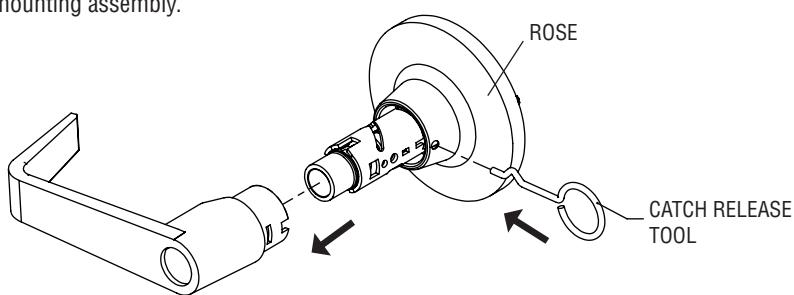
6. REMOVE INSIDE MOUNTING ASSEMBLY
Use catch release tool (provided) to depress inside lever catch through hole of inside trim collar. Pull lever off of inside mounting assembly. Remove inside rose from the mounting assembly.
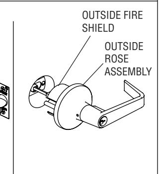
7. INSTALL OUTSIDE LEVER
Place outside lever over the hole in the door face, inserting spindle through latch. Press outside rose assembly flush against door. NOTE: For proper installation, verify outside fire shield is fully seated in the outside rose assembly.
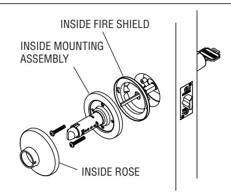
8. INSTALL INTERIOR MOUNTING ASSEMBLY
Insert and fully seat inside fire shield into inside mounting assembly. Align inside mounting assembly with spindle and screw posts. Verify catch release button is pointing in the direction of the lock stile and slide on until flush with face of door. Place mounting screws into holes and tighten securely.
Snap the inside rose onto the mounting assembly (for proper fit, be sure to fit notches in the rose into the recesses on the mounting assembly).
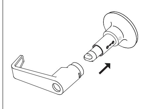
9. INSTALL INSIDE LEVER
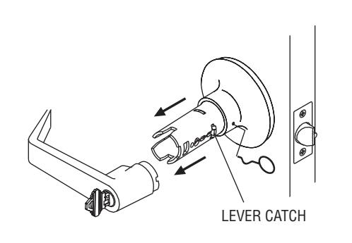
10. INSTALL CYLINDER (SKIP THIS STEP FOR 3610 AND 3640)
Push inside lever all the way until catch clicks into catch slot.
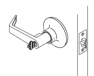
A. Turn key clockwise 1/4 turn. B. Using catch release tool, press the lever catch and pull the lever off.
REV 2 Page 2 of 2