3500 Knobset Installation Instructions – I-LS00767
Open the original PDF document
View PDF

3500 Series ANSI Grade 2 Knob Set Installation Instructions Meets ANSI 156.2 I-LS00767
For use on doors 1-3/8" to 1-3/4" (35 mm - 45 mm) thick
TOOLS REQUIRED FOR NEW INSTALLATION:
- (1) Phillips Head Screwdriver
- (1) 2-1/8" (54 mm) Hole Saw
- (1) 1" (25.4 mm) Drill Bit
- (1) Chisel
- (1) Catch-Release Tool (Provided)
- (1) Hex Wrench (Provided)
TOOLS REQUIRED FOR REPLACEMENT INSTALLATION:
(1) Phillips Head Screwdriver
FOR REMODELING OR NEW CONSTRUCTION:
-Follow all steps
FOR REPLACEMENT OF EXISTING LOCK:
-Follow steps 3C, 4C, 5 through 9 after removal of old lock
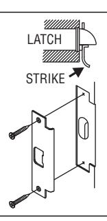
1. MARK DOOR
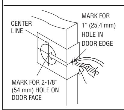
Measure center line of lock; height as desired from finished floor. Select 2-3/4" or optional 2-3/8" backset, fold and apply template to high side of bevel of door and mark center of door edge as indicated on template. Mark center hole on door face through guide on template.
2. DRILL HOLES
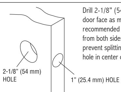
Drill 2-1/8" (54 mm) hole through door face as marked for lockset. (It is recommended that holes be drilled from both sides on wood doors to prevent splitting.) Drill 1" (25.4 mm) hole in center of door edge for latch.
3. INSTALL LATCH
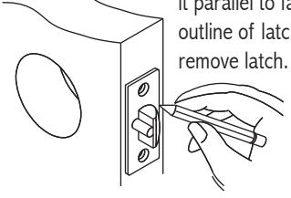
A. Insert latch in hole keeping it parallel to face of door. Mark outline of latch face plate and
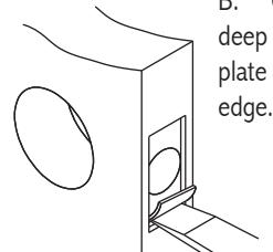
B. Chisel 5/32" (4 mm) deep or until latch face plate is flush with door
C. Insert latch and tighten to the door using #8 screws. NOTE: Latchbolt bevel must face to closing direction.
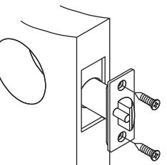
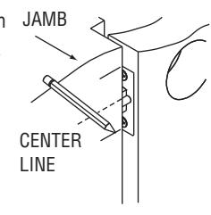
4. INSTALL STRIKE
A. Close door until latchbolt touches jamb. Locate strike in jamb and center line of strike. Open door and extend line to door stop. Measure one half of door thickness plus 1/8" from door stop. Vertically mark center line for strike.
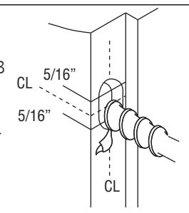
B. Drill two (2) 1" (25.4 mm) holes 3/4" (19 mm) deep in door jamb 5/16" (8 mm) below horizontal center line.
CAUTION: To ensure proper lockset function, hole in jamb must be drilled a full 3/4" (19 mm) deep.
C. Cut out jamb mortise for strike 3/32" (2.4 mm) deep or until strike is flush with jamb. Tighten to the frame using #12 screws.
REV 2 Page 1 of 2

3500 Series ANSI Grade 2 Knob Set Installation Instructions Meets ANSI 156.2 I-LS00767
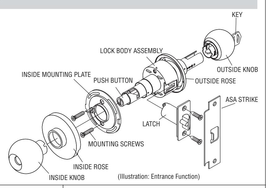
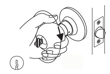
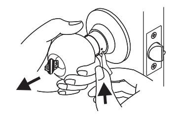
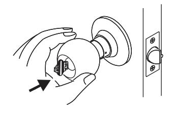
5. REMOVE INSIDE TRIM
CATCH RELEASE TOOL
A. Use nail end of catch release tool provided to depress inside knob catch in hole of inside sleeve collar and slide knob off spindle.
INSIDE ROSE ASSEMBLY
B. Remove inside rose assembly.
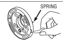
C. Depress spring attached to inside rose. Insert nail end of catch release tool into slot to remove inside rose plate.
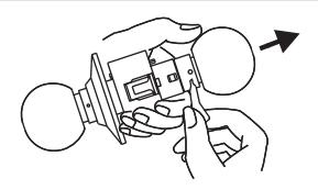
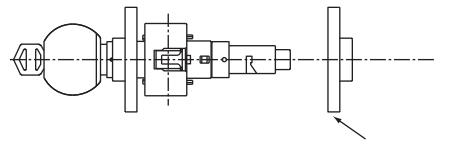
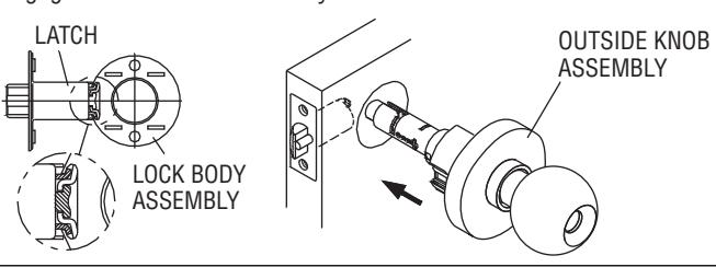
6. INSTALL OUTSIDE KNOB ASSEMBLY
Install outside knob assembly on the door. Make sure tail of latch engages with retractor correctly as illustrated.
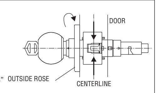
7. ADJUST OUTSIDE ROSE
Lock is pre-set for 1-3/4" door thickness. To fit different door thickness, adjust lock to fit door thickness by rotating outside rose until latch retractor is centered on door centerline. Lock will fit all doors 1-3/8" to 1-3/4" (35 mm - 45 mm) thick.
8. INSTALL INSIDE ROSE AND KNOB
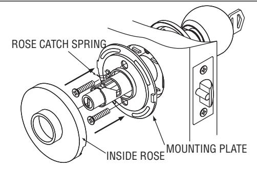
A. Rotate mounting plate so rose catch spring is facing opposite the lock stile and slide on until flush with door. Tighten machine screws securely to install mounting plate. Press rose onto mounting plate. Be sure to fit rose in recess of mounting plate.
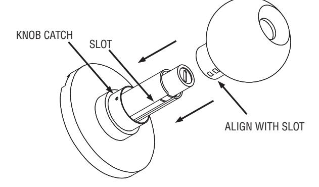
B. To install inside knob, align inside knob with slot and push all the way down until knob locks in place.
9. INSTALL CYLINDER
In the event the keyway was installed in the incorrect, upward position, the knob must be pulled out and installed again. The method of installation is as described below. (NOTE: If installing a 3580 lockset, ignore Step B, and ensure that the key is held in the horizontal position in Step C.)
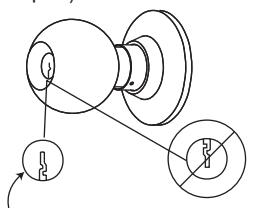
CORRECT KEYWAY POSITION
A. Verify keyway is in the downward position. If not, proceed to steps 9B through 9D.
B. Insert key in cylinder. Turn knob clockwise until the Knob Catch appears in the small hole. Use key to ensure cylinder remains in the vertical position.
C. Using catch release tool, press the knob catch and pull the knob off.
D. Install with keyhole facing downward.
REV 2 Page 2 of 2