3216 Installation Instruction I-LS01680
Open the original PDF document
View PDF

3216 Indicator Deadlock Installation Instructions I-LS01680
For use on doors 1-3/8" to 1-3/4" (35-45 mm) thick
Tools required for new installation:
- (1) Phillips head screwdriver
- (1) 2-1/8" (54 mm) hole saw
- (1) 1" (25.4 mm) drill bit
- (1) chisel
Tools required for replacement installation:
(1) Phillips head screwdriver
For remodeling or new construction: Follow all steps.
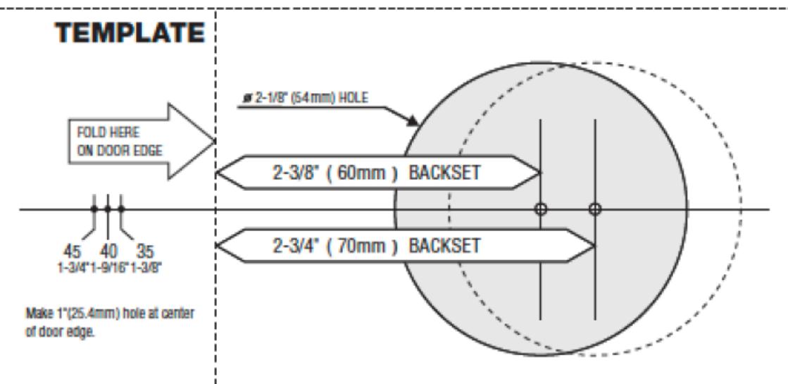
1. MARK DOOR
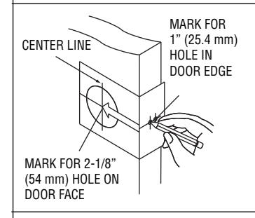
Measure center line of lock; height as desired from finished floor. Select 2-3/4" or optional 2-3/8" backset, fold and apply template to interior side of door and mark center of door as indicated on template. Mark center hole on door face through guide on template.
2. DRILL HOLES
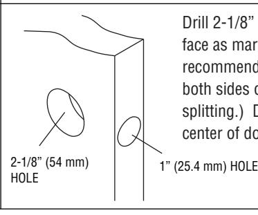
Drill 2-1/8" (54 mm) hole through door face as marked for lockset. (It is recommended that holes be drilled from both sides on wood doors to prevent splitting.) Drill 1" (25.4 mm) hole in center of door edge for latch.
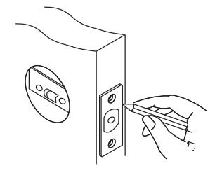
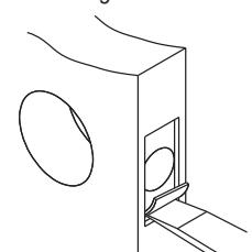
3. INSTALL LATCH
- A. Insert latch in hole, keeping it parallel to face of door. Mark outline of latch face plate and remove latch.
- B. Chisel 5/32" (4 mm) deep or until latch face plate is flush with door edge.
- C. Insert latch and tighten to the door using #8 screws.

3216 Indicator Deadlock Installation Instructions I-LS01680
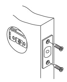
4. INSTALL STRIKE
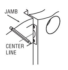
Close door. Locate strike in jamb and center line of strike. Open door and extend line to door stop. Measure half of door thickness plus 1/8" from door stop. Vertically mark centerline for strike.
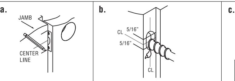
Drill (2) 1"(25.4 mm) holes 1-1/4" (31.7 mm) deep in door jamb, 5/16" (8 mm) above and 5/16'" (8 mm) below horizontal center line.
CAUTION:
Hole must be drilled a full 1-1/4" (31.7 mm) deep to ensure proper functioning.
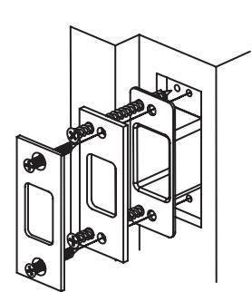
Match screw holes on strike with vertical centerlines on jamb. Mark outline of strike and chisel 1/4" (6.4mm) deep for flush fit of dust box, wood frame reinforcer, and strike. Place dust box and wood frame reinforcer into mortised area and tighten to the frame using 3" wood screws. Insert the strike and tighten to the frame with #8 screws.
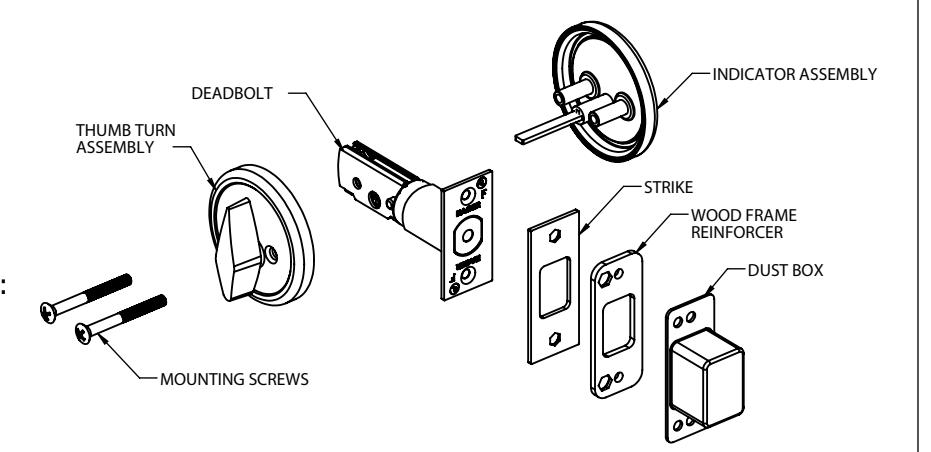
5. INSTALL THUMBTURN ASSEMBLY AND BLANK PLATE
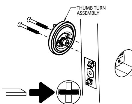
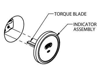
Insert torque blade horizontally into deadbolt latch. Crank until indicator assy is flush with the door face. Mate the thumbturn assembly with the torque blade on the indicator assembly. Insert the screws thru the holes of the thumbturn assembly and latch body. Tighten the screws to the threaded posts of the blank mounting plate. Tighten the assembly so the complete assembly is tight to the door.
6. BACKSET ADJUSTMENT
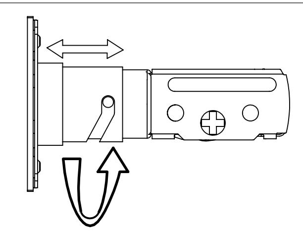
To change deadbolt to a 2-3/8" backset, rotate faceplate 1/2 turn.