3215_3214 Series Installation Instruction – I-LS00764
Open the original PDF document
View PDF

3200 Series ANSI Grade 2 Deadbolt Installation Instructions Meets ANSI 156.5 I-LS00764
For use on doors 1-3/8" to 1-3/4" (35 mm - 45 mm) thick
TOOLS REQUIRED FOR NEW INSTALLATION:
- (1) Phillips Head Screwdriver
- (1) 2-1/8" (54 mm) Hole Saw
- (1) 1" (25.4 mm) Drill Bit
- (1) Chisel
TOOLS REQUIRED FOR REPLACEMENT INSTALLATION:
(1) Phillips Head Screwdriver
FOR REMODELING OR NEW CONSTRUCTION:
-Follow all steps
FOR REPLACEMENT OF EXISTING LOCK:
-Follow steps 3C, 4C, and 5 (single cylinder) or 6 (double cylinder) after removal of old lock
NOTE: When installing an IC Core single cylinder deadbolt to a 1-3/8" thick door, you must install provided spacer
ring behind the cylinder assembly for proper spacing.
1. MARK DOOR
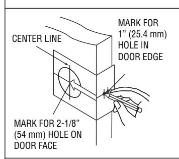
Measure center line of lock; height as desired from finished floor. Select 2-3/4" or optional 2-3/8" backset, fold and apply template to high side of bevel door and mark center of door edge as indicated on template. Mark center hole on door face through guide on template.
2. DRILL HOLES
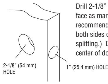
Drill 2-1/8" (54 mm) hole through door face as marked for deadbolt. (It is recommended that holes be drilled from both sides on wood doors to prevent splitting.) Drill 1" (25.4 mm) hole in center of door edge for latch.
3. INSTALL LATCH
- A. Insert latch in hole keeping it parallel to face of door. Mark outline of latch face plate and remove latch.
- B. Chisel 5/32" (4 mm) deep or until latch face plate is flush with door edge.
- C. Insert latch and tighten to the door using #8 screws.

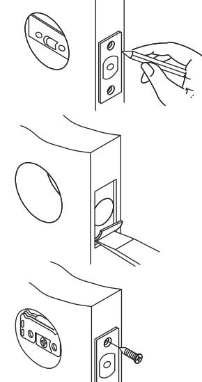
4. INSTALL STRIKE
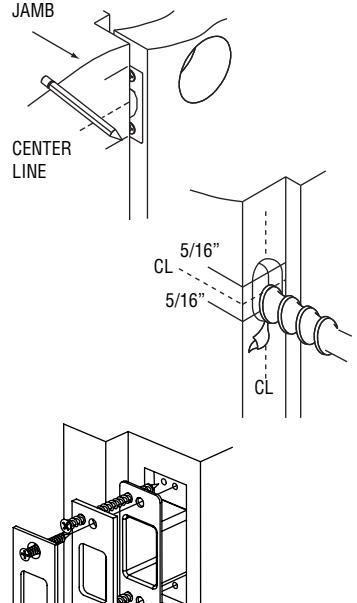
- A. Close door. Locate strike in jamb and center line of strike. Open door and extend line to door stop. Measure one half of door thickness plus 1/8" from door stop. Vertically mark center line for strike.
- B Drill two 1" (25.4 mm) holes 1-1/4" (32 mm) deep in door jamb and 5/16" (8 mm) above and 5/16" (8 mm) below horizontal center line. CAUTION: To ensure proper lockset function, hole in jamb must be drilled a full 1-1/4" (32 mm) deep.
- C. Match screw holes on strike with vertical centerlines on jamb. Mark outline of strike and chisel 1/4" (6.4 mm) deep for flush fit of dust box, wood frame reinforcer, and strike. Place dust box and wood frame reinforcer into mortised area and tighten to the frame using 3" wood screws. Insert the strike and tighten to the frame with #8 screws. NOTE: Mortise 5/64" (2 mm) deep if mounting strike plate only.
REV 2 Page 1 of 2

3200 Series ANSI Grade 2 Deadbolt Installation Instructions Meets ANSI 156.5 I-LS00764
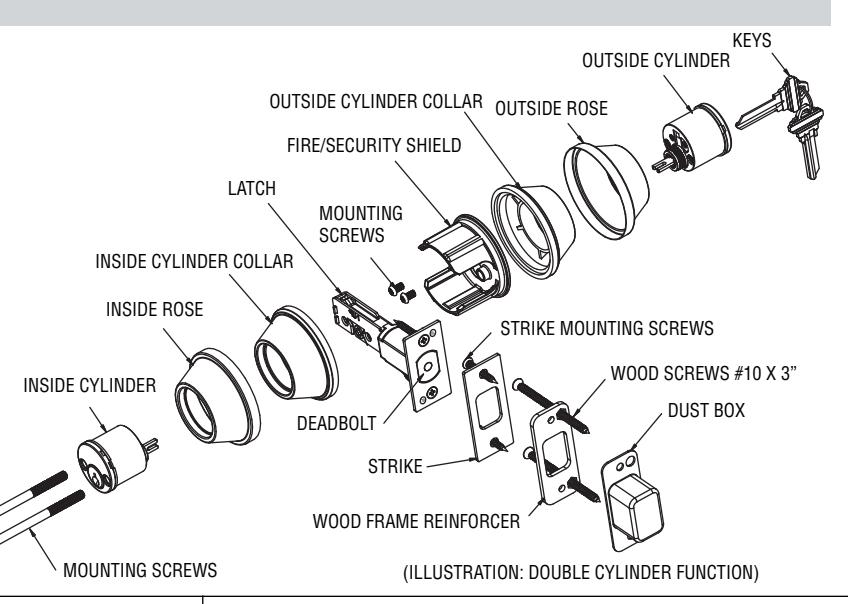
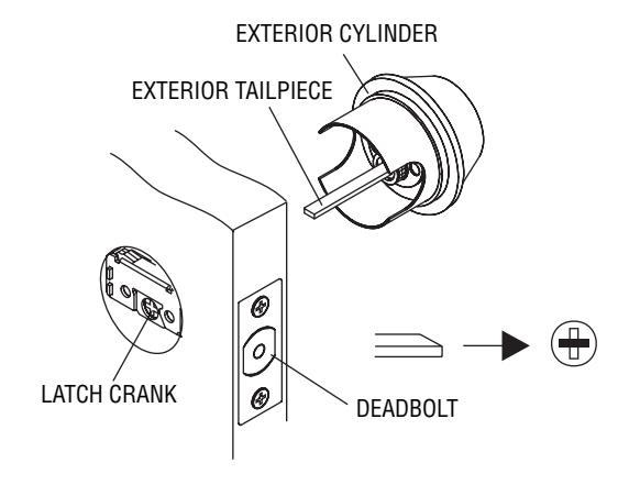
5. INSTALL SINGLE CYLINDER (SKIP TO STEP 6 IF USING DOUBLE CYLINDER)
A. Retract deadbolt to unlock position. Insert exterior tail piece horizontally through latch crank.

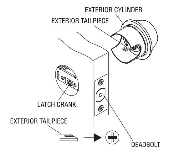
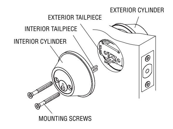
6. INSTALL DOUBLE CYLINDER
A. Retract deadbolt to unlock position. Insert exterior tail piece horizontally through latch crank.
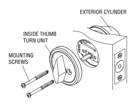
B. Press exterior cylinder flush against door. Install interior tail piece vertically through latch crank. Press interior cylinder flush against door and tighten mounting screws.

REV 2 Page 2 of 2