30 Series Electric Strikes Installation Instructions
Open the original PDF document
View PDF

[t] 800.413.8783 ■ 805.494.0622 ■ E-mail: service@sdcsecurity.com ■ 801 Avenida Acaso, Camarillo, CA 93012 ■ PO Box 3670, Camarillo, CA 93011
INSTALLATION INSTRUCTIONS
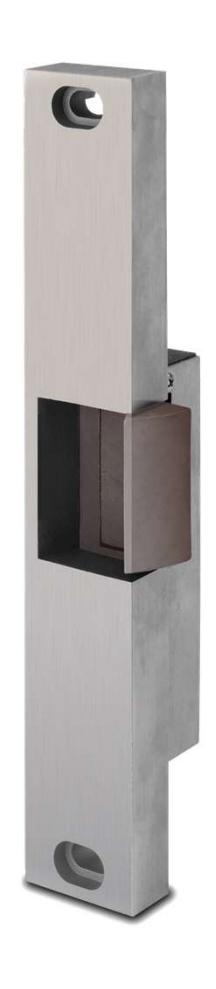
30-4 RIM MOUNT ELECTRIC STRIKE
Specifications:
Voltage: .51 Amps @ 12 VDC
.25 Amps @ 24 VDC
Models: 30 – 4 – 12
30 – 4 – 24
Options: FS – Fail-Safe
LCBMA-30 – Latch & Locking cam monitoring

CAUTION!
Before connecting any device at the installation site, verify input voltage using a multimeter. Many power supplies and low voltage transformers operate at higher levels than listed. Any input voltage exceeding 10% of the solenoid rating may cause severe damage to the unit and will void the warranty.
Preparing the Strike
- 1. Attach the faceplate to the strike body using the #12-24 x 3/8" Body Mounting screws as illustrated on Page 3.
- 2. IF using the LCBMA (Latchbolt & Locking Cam Monitor), See Image below for wiring instructions.
NOTE:
The strike body ships as either a 12 or 24 volt unit and is not field selectable.
3. VERIFY the available voltage is +/- 10% of the rated voltage of the strike body.
Preparing the Strike
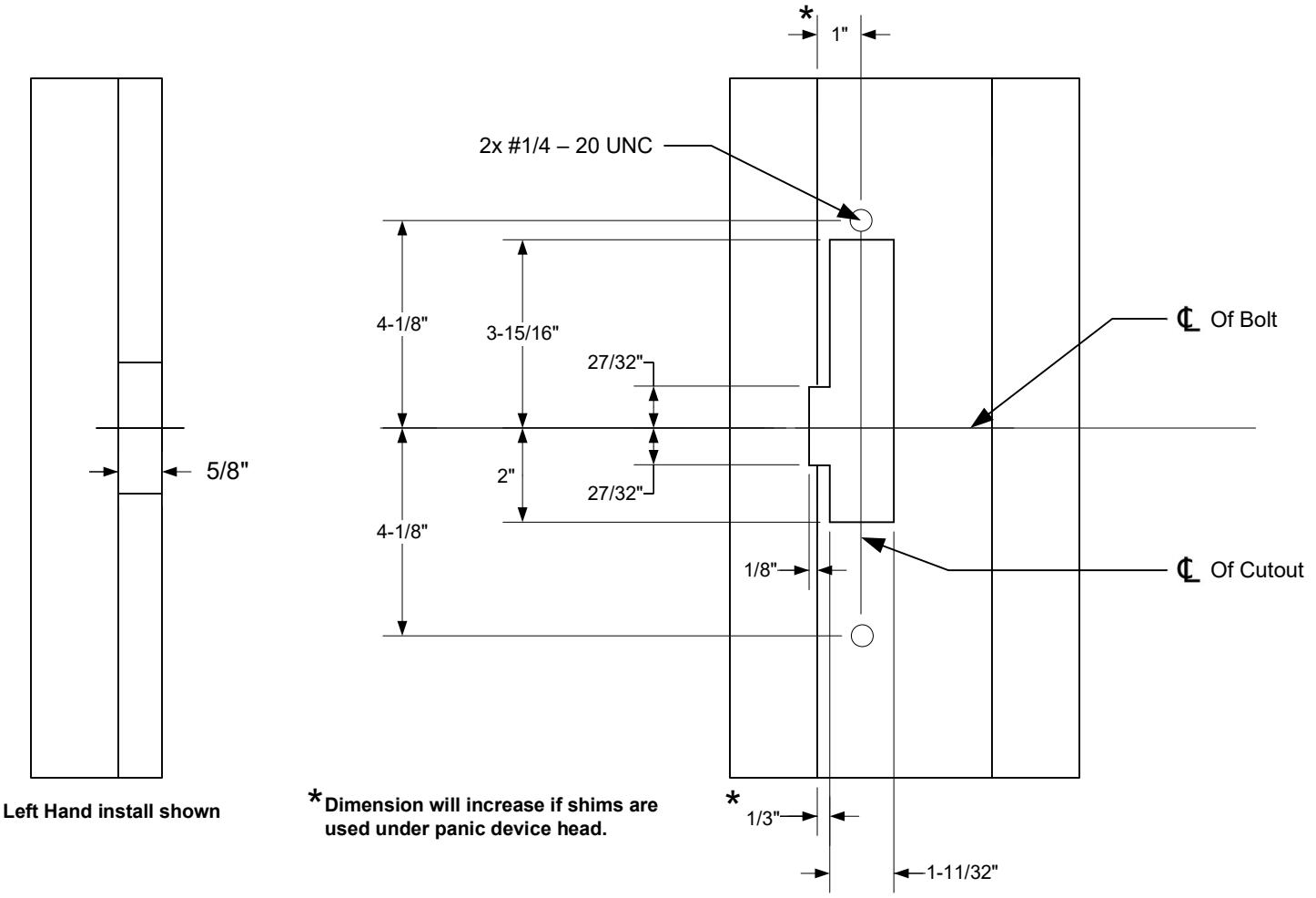
- 4. PREPARE frame using the dimensional reference on Page 4.
- 5. TEST FIT the electric strike in the door frame.
- 6. IF there is not enough clearance between the exit device and the door strike, THEN REMOVE the spacer plate as shown on Page 3.
Finishing the Installation
- 7. CONNECT the Plug in Connector to the electric strike and CONNECT wires from the Plug in Connector leads to the power source.
- 8. INSTALL the electric strike unit in jamb cutout, using the provided #12-24 x 1/2" faceplate mounting screws
- 9. ADJUST the strike horizontally as shown on Page 3. to accommodate any door silencers or smoke seals
Monitoring Switches
Locking Cam Monitor (LCM) Latchbolt Monitor (LBM)
White: COM Brown: COM N/O Orange: N/O Blue: Green: N/C Yellow: N/C
* When secured
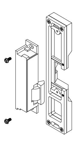
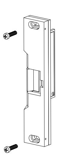
Attaching the Faceplate
- 1. To attach the 30-4 series electric strike body to the faceplate, INSTALL with two #8-32 body mounting screws as shown.
- 2. ADJUST the keeper position as needed before tightening screws.
- 3. ENSURE body mounting screws are tightened and secured after adjustment is made.
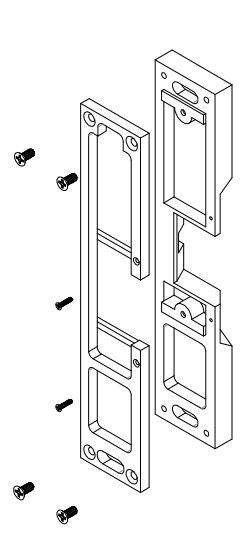
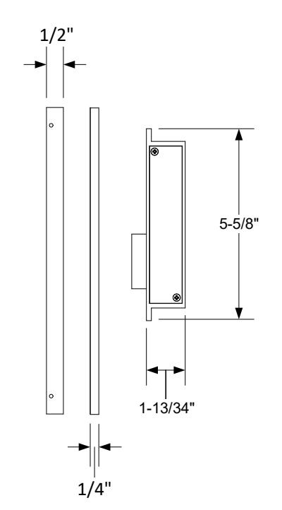
Removing the 1/4" Spacer Plate
NOTE:
A 1/ 4" spacer plate is preinstalled to the strike faceplate. Removal of the spacer plate will decrease faceplate thickness from 3/4" to 1/2".
- 1. REMOVE the four #8-32 screws and two #2-56 screws.
- 2. REMOVE the spacer plate.
Adjusting the Horizontal
- 1. LOOSEN the two #1/4 20 faceplate mounting screws.
- 2. ADJUST the strike to the appropriate position.
- 3. TIGHTEN the two #1 4 20 faceplate mounting screws.
NOTE:
A 3/8" setscrew are provided. Proper selection will secure the #1/ 4 – 20 faceplate mounting screws, but not protrude from the strike body.
4. LOCK DOWN the adjustment by installing the provided set screws.

Strike Dimensions
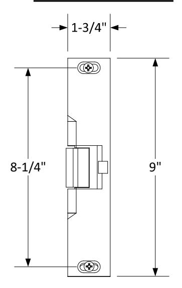
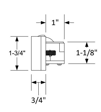
Dimensional Drawing Only Not Drawn to Scale
Frame Dimensional Cutout