2945-Rim_Strike_Installations_Instruction
Open the original PDF document
View PDF

Electrified Locks
Hager 2945 Electric Preload RIM Strike
INSTALLATION INSTRUCTIONS
THIS PACKAGE INCLUDES:
2 - 4-PIN power connector
1 - 3-PIN door status connector
1 - Installation Jig
4 - 1/4 - 20 x 1-1/4'' Screws
4 - M3 x 6 Screws 2-#10x 1-1/2" flat
1 - MOV head screws
1 - Cover plate
1- Spacer
1. GENERAL DESCRIPTION
Hager 2945 Preload RIM strike for pullman latches offers the very best strike quality and performance. The strike design delivers unparalleled application flexibility, with field selectable voltage, fail safe/fail secure operation and mechanical adjustment of the strike body.
2. SPECIFICATIONS
| Voltage | 12/24V AC/DC |
|---|---|
| Current Draw |
560mA @ 12 VDC
280mA @ 24 VDC |
| Static Strength | 1,500lbs. (UL Verified) |
| Dynamic Strength | 70 ft-lbs. |
| Preload (Fail-Secure Only) | 15lbs. |
| Endurance |
1,000,000 Cycles (Factory Tested)
500,000 Cycles (UL Verified) |
| Latch Projection | 3/4" |
| Fire Rating |
UL 10C/CAN4-S104
3 hrs. (Fail Secure Only) |
| Mode |
Field Selectable
Fail Safe/Fail Secure |
| Mechanical Adjustment | Strike Body |
| Operation | AC-Buzz, DC-Silent |
| Duty | Continuous |
| Latch Bolt Monitor |
SPDT, 100mA @ 24V DC
Resistive |
| Dimensions (Body) |
9-3/16"H x 1-15/16"W x
3/4"D (233mm x 49mm x 20mm) |
3. DIMENSIONS
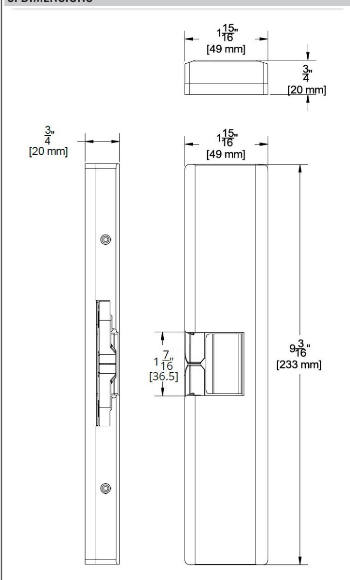
Figure 3.1 Dimensions
4. INSTALLATION
Introduction
RIM electric strikes used with Pullman latch devices (i.e. exit devices) are very different from installing an electric strike for cylindrical or mortise lock sets, and therefore require additional considerations and a different installation technique.
Hager 2945 is designed to allow up to 15 lbs of preload on the strike keepers. This unique feature eliminates typical installation challenges caused by warped or misaligned doors, frames or locking hardware. For detailed installation instructions for the 4500 exit device refer to template T-ED04039. For detailed instructions of the 4600 refer to T-ED04037. For detailed instructions of the 4700 refer to template T-ED04036. All product documentation can be found online at Hagerco.com.
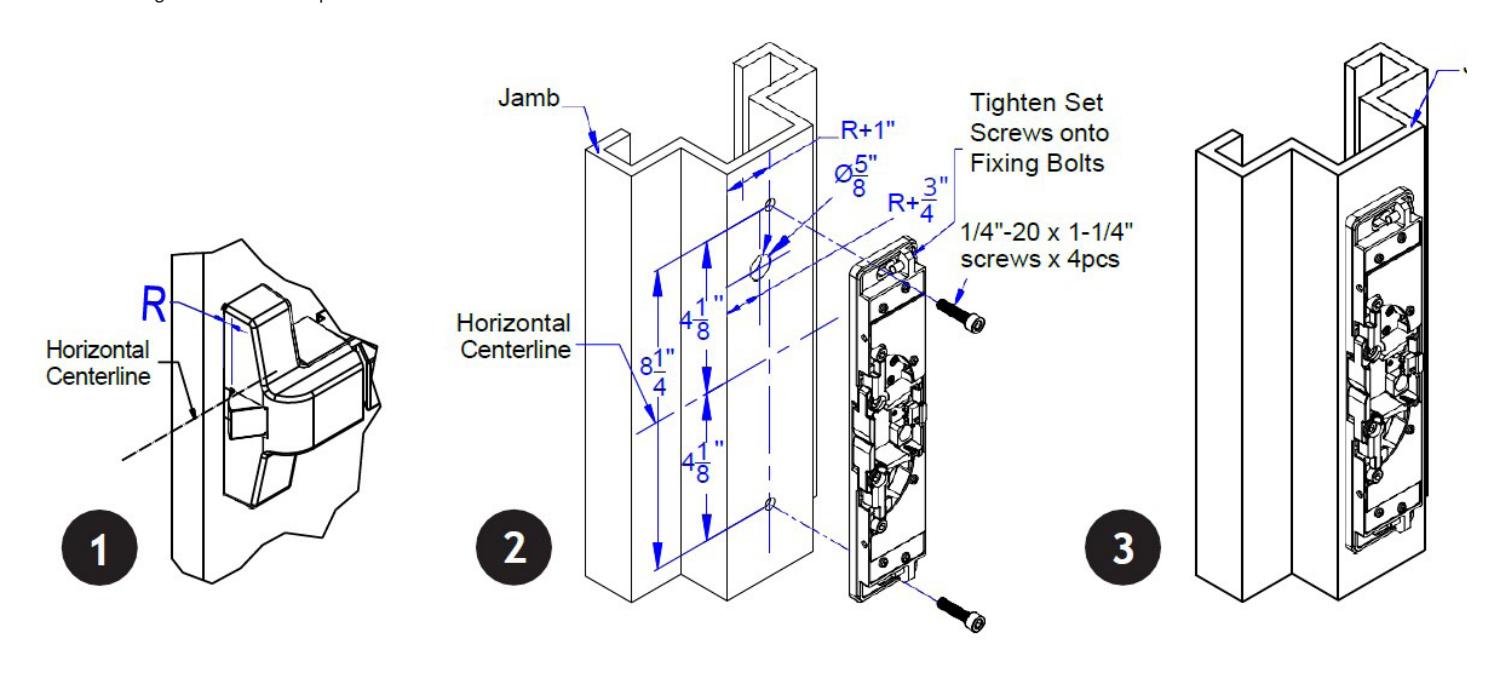
Step 1: Using the Install Jig
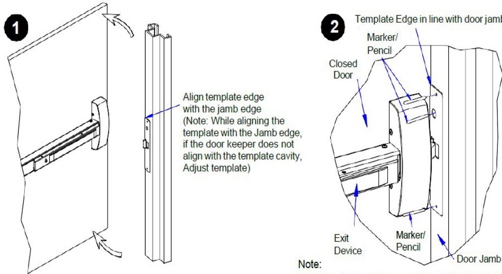
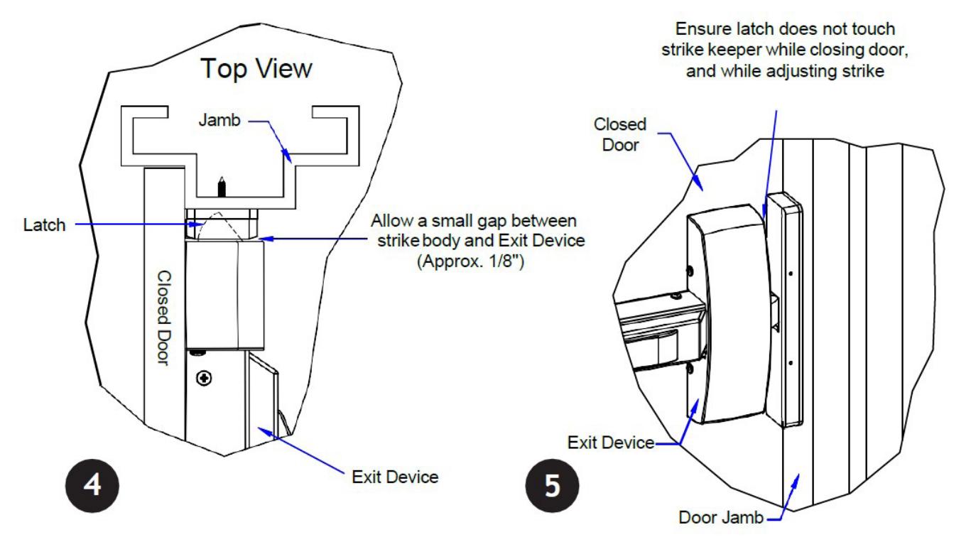
Step 2: Aligning the Strike
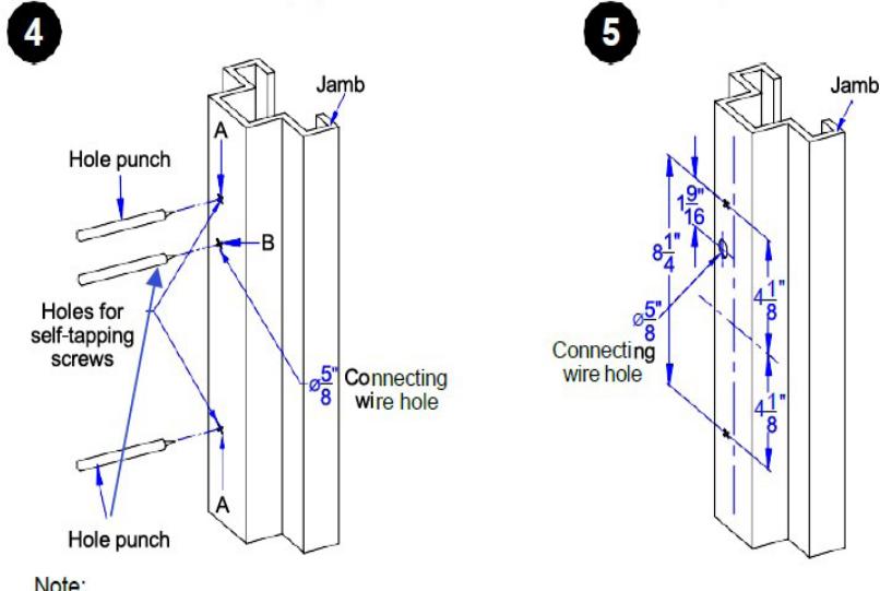
- 1. Mark the location and drill the 5/8" diameter hole for the electrical cable as per template or dimensions shown below.
- 2. Secure stike in place with the 1/4"-20 x 1-1/4" screws (2).
- 3. Close the door (ensure exit device latch does not touch keeper while closing the door). If necessary, adjust strike so that strike and exit device latch are well aligned.
- 4. While adjusting the strike, allow a small gap between strike body and exit device (approximately 1/8"). Remove the latch on strike and mark the remaining two middle screw positions on frame.
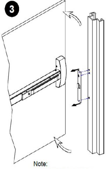
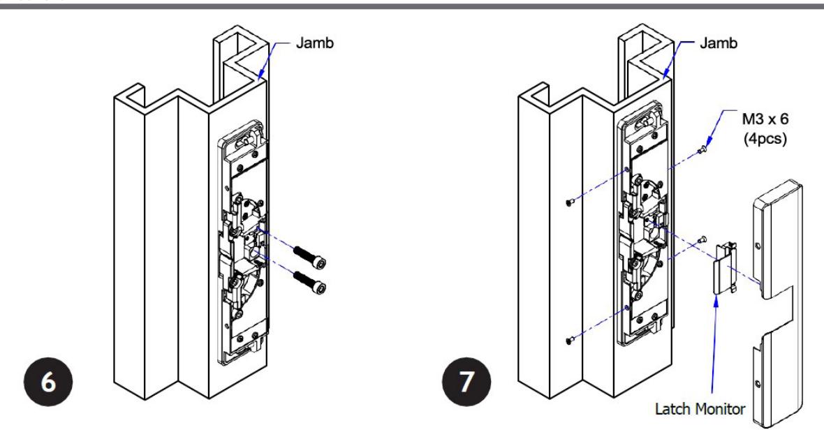
- 5. Open the door and remove the strike from the frame, drill and thread the two middle mounting screw holes and thread for the 1/4"-20 x 1-1/4" screws.
- 6. Secure strike with all 1/4"-20 x 1-1/4" screws to secure the strike base. Use the M3 x 6 screws to secure the strike cover.
Note:
The products are intended to be installed in accordance with the installation wiring diagram, mechanical assembly drawings provided with each product, the local authority having jurisdiction (AHJ) and the National Electric Code, NFPA 70.
When installed in fail secure mode, the local authority shall be consulted with regard to the use of possible panic hardware to allow emergency exit from the secure area.
The electric door strike shall be installed in such a way and in such location so as to not impair the operation of an emergency exit device or panic hardware mounted on the door.
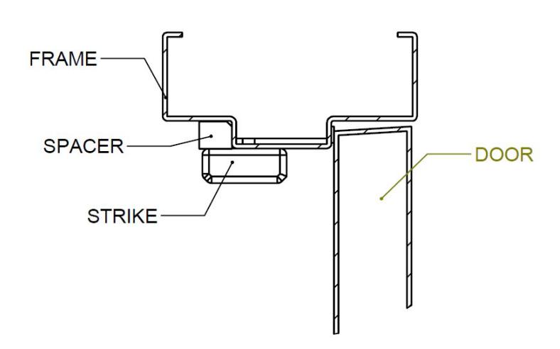
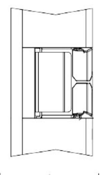
For R values greater than 5/8", you may install the optional spacer bar to fill the resulting gap between the frame and strike. See the diagram below for installation.
For Product specific installation instructions please refer to the templates found at www.Hagerco.com Optional step:Install spacer
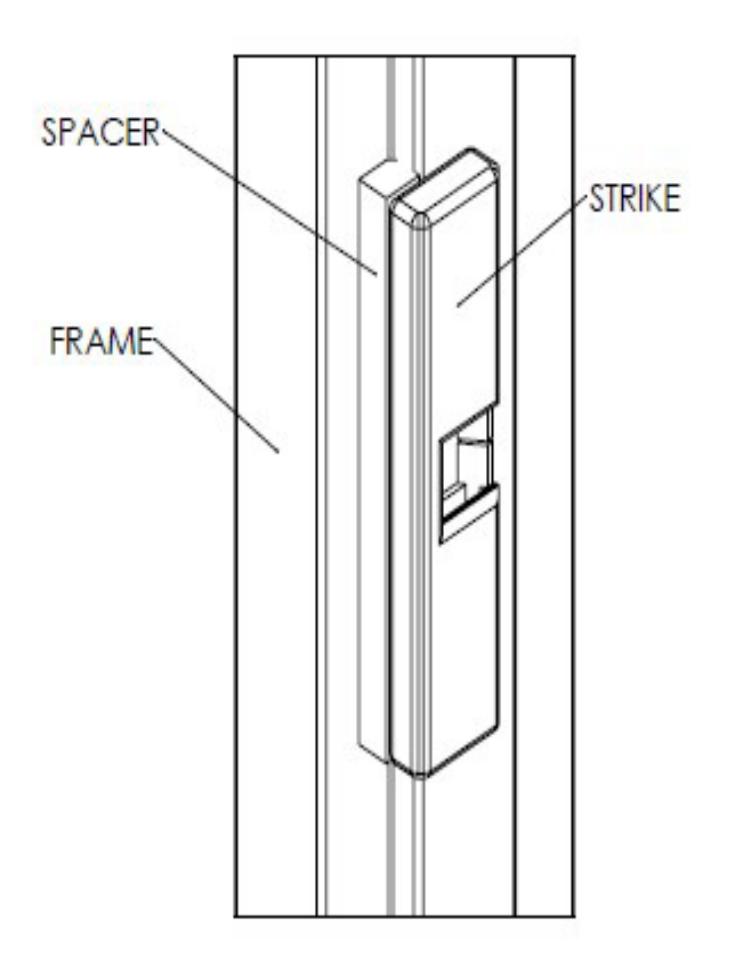
- 1. Before installing the cover on the strike, slide the spacer towards the frame stop. Orient the spacer with the notched corner between the strike and frame. Ensure that the top and bottom of the spacer are flush with the strike.
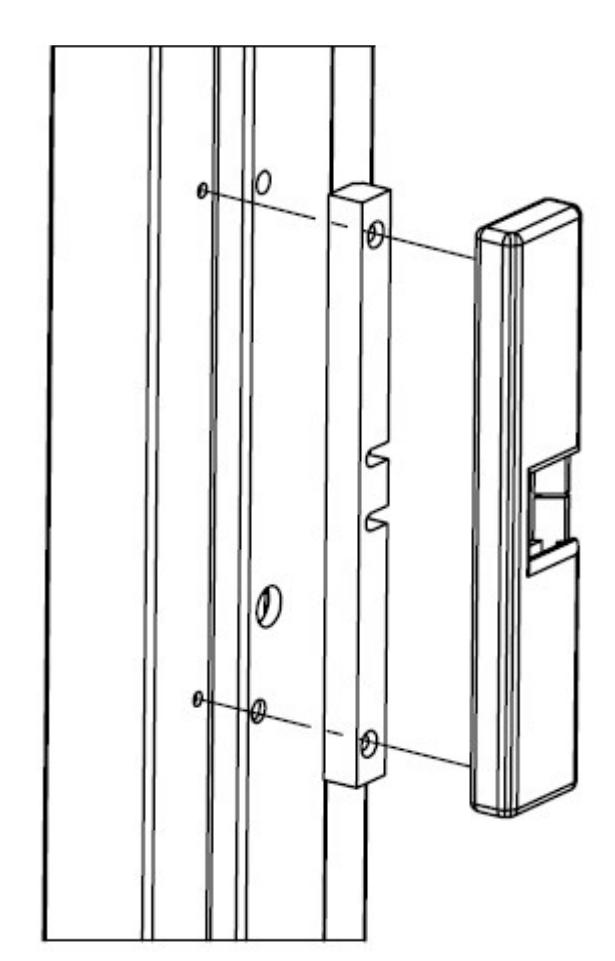
- 2. Mark the location of the strike on the frame and remove the strike.
- 3. Dimple the frame with a center punch to prepare the top and bottom spacer holes for drilling.
- 4. Drill the marked holes with a Ø1/8" bit. Place the spacer back on the frame, again ensuring the notch is in the frame corner. Fasten the spacer using the top and bottom mounting screws.
- 5. Mount the strike on the frame as per the instructions.
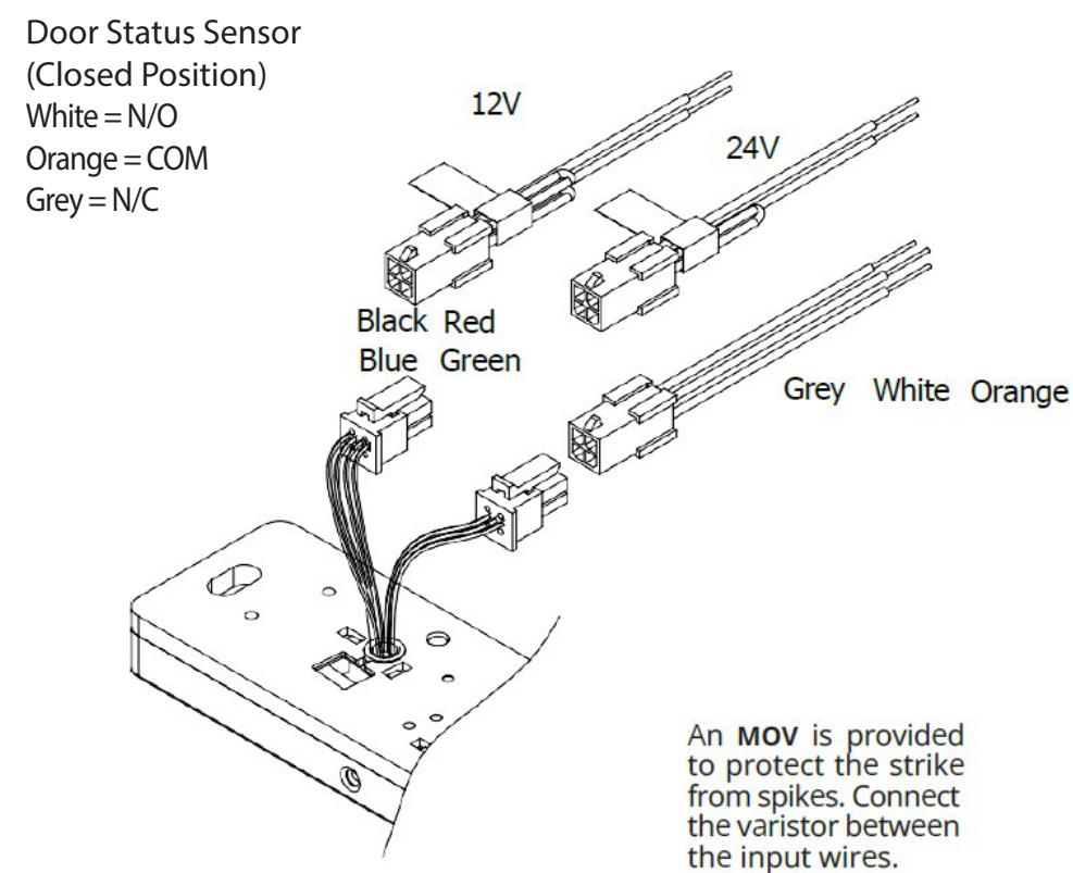
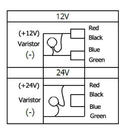
Step 3: Wiring the Strike
Step 4: Setting Fail-Secure/Fail-Safe
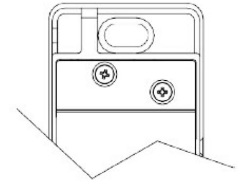
How to modify fail-secure to fail-safe or vice versa.
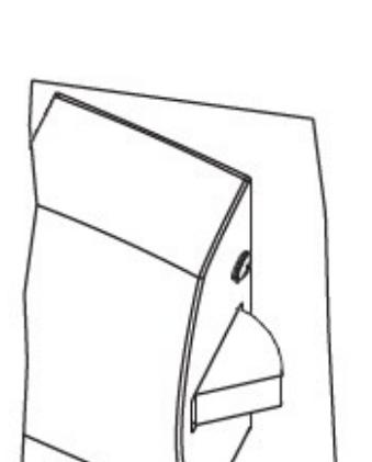
- 1. Remove the cover plate. Remove the six screws at the front of the electric strike as per the diagram to the right.
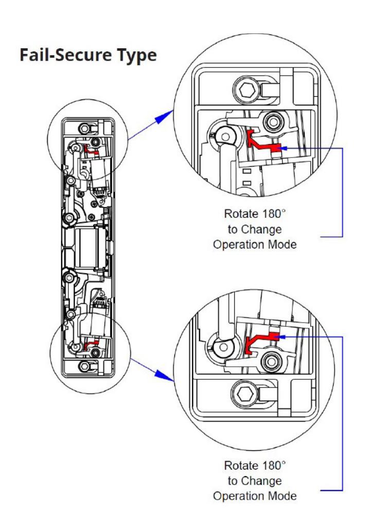
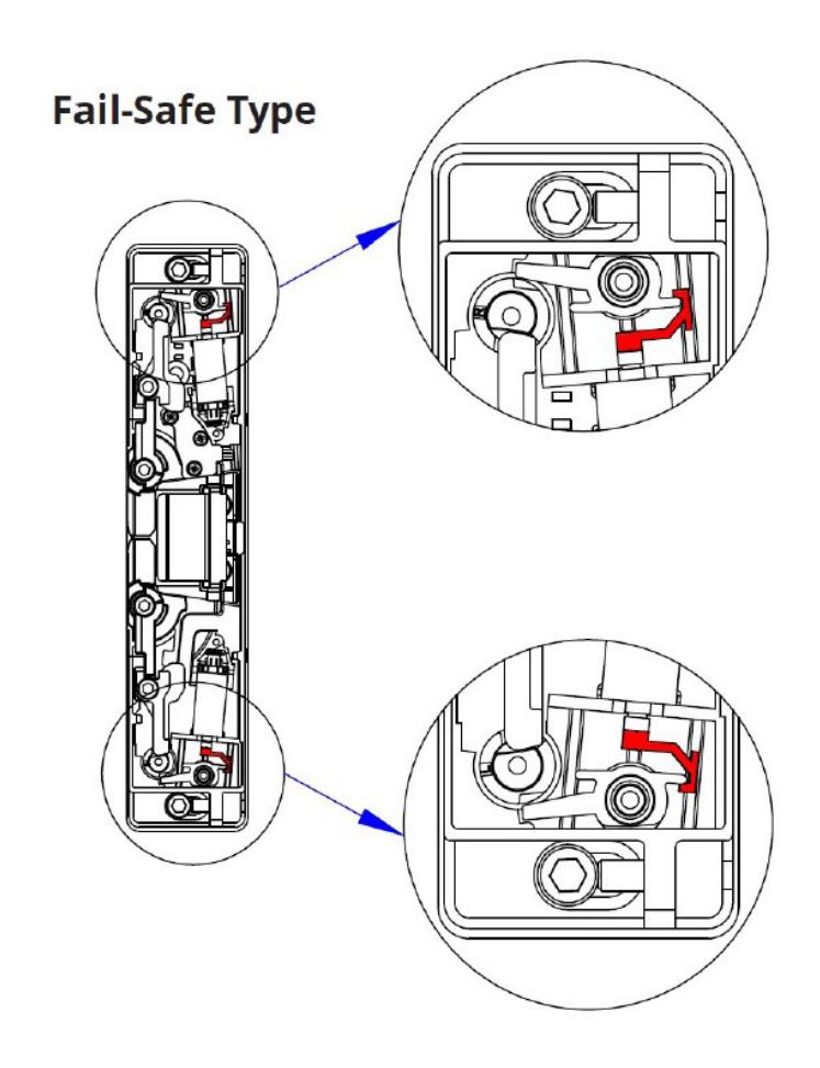
- 2. Rotate status mechanism 180 degree to change operation mode.
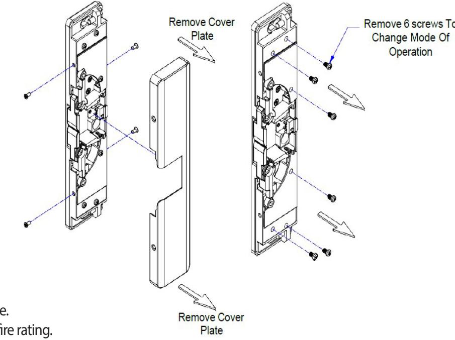
Note: Strikes are shipped fail-secure. Changing to fail-safe voids the UL fire rating.
5. TROUBLESHOOTING
This guide has been produced to help installers understand the most important physical considerations that need to be addressed when installing the Hager 2945 RIM strike.
Step 1: Confirm Latch entry to rim strike
The position of the latch held by the RIM strike is of critical importance to the operation of the strike. The most important considerations, and potential causes of failure, are as follows:
- The Exit device latch MUST NOT apply excessive pressure on the keeper (jaws) of the RIM strike. Pre-load pressure exceeding 15lbf on the strike jaws will prevent strike operation - it is the most common reason for a strike failing. Position the RIM strike so that the strike jaws lightly rest against the latch of the exit device.
- The exit device latch MUST depress (activate) the latch monitor 'paddle' of the RIM strike. If the latch monitor is not used, this placement insures the latch of the exit device is fully held by the keeper (jaws) of the strike.
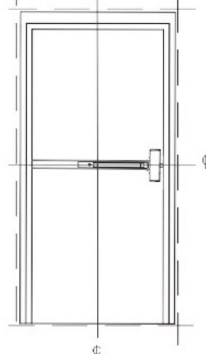
Step 2: Confirm Door Alignment
Virtually all of Hager's electric strike models, including the Hager 2945 RIM strike, offer horizontal adjustment, to compensate for doors that are misaligned with the door frame - but there is a limit to the strike adjustment.
- Check that the door is not binding on the frame. An electric strike cannot compensate for this. If present, the door hinges will need to be adjusted.
- Check the gap between the door and the stop of the frame (where the top and at the bottom of the door). A 1/4" difference in gap is very common and can be compensated for by the strike - if installed correctly.
- If the door stop gap at the top and bottom of the door is different, the electric strike cannot be installed plumb ('straight' up and down). The horizontal orientation of the RIM strike will need to be adjusted to match the angle of the misaligned door.
To do this:
- Mount RIM strike in the position on frame, using only the (2) center (elongated) screw holes, top and bottom.
- Rotate the strike until both jaws of the strike very lightly touch the exit device latch, with equal gap, on both jaws.
- Tighten center screws and open/close door to confim latch does not bind on the strike jaws.
- Affix the 4 screws that permanently mount strike on the frame.

Although the considerations above will address the majority of installation steps needed for a successful installation, there are additional things that you will need to check for:
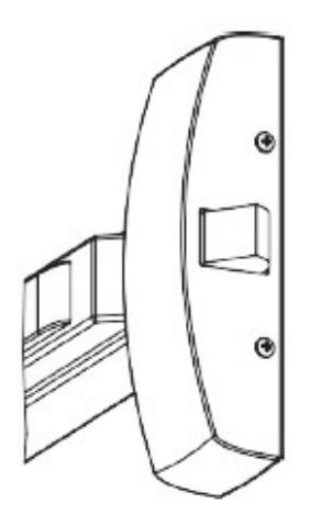
- Consideration for deadlocking latch (as shown here). If the exit device has a deadlocking latch, the 2945 must be mounted so that the deadlocking latch does not enter the latch cavity of the rim strike. Position the strike so that the deadlocking latch rests against the face of the strike.
- Consideration of the free movement of the exit device latch and the keeper (jaws) of the RIM strike.
Ensure the exit device latch and the keeper (jaws) of the electric strike have free and easy movement to operate together, with minimum friction. In this, a small amount of silicone lubricate on both the latch and jaws of the strike will improve operation. Do not over spray.
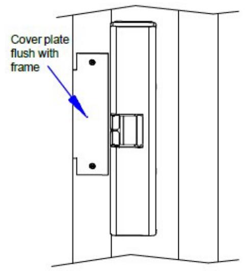
• Consideration for a professionally finished retrofit installation. Replacing electric strikes used with cylindrical or mortise locksets, with an exit device and RIM strike, will leave holes in the door and door frame that must be filled or covered. Cover or plug holes and check that new cover plates are flush with the frame and will not interfere with the RIM strike.

Adherence with the recommendations of this guide will avoid the most common problems associated with the installation of RIM strikes. If you require additional assistance, please contact our Technical Support department by phone at 800-255-3590 or email support@Hagerco.com