2928 Installation Instructions i-ea00077-rev2
Open the original PDF document
View PDF

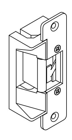
INSTALLATION INSTRUCTIONS 2928 SERIES ELECTRIC STRIKES
MODELS:
-
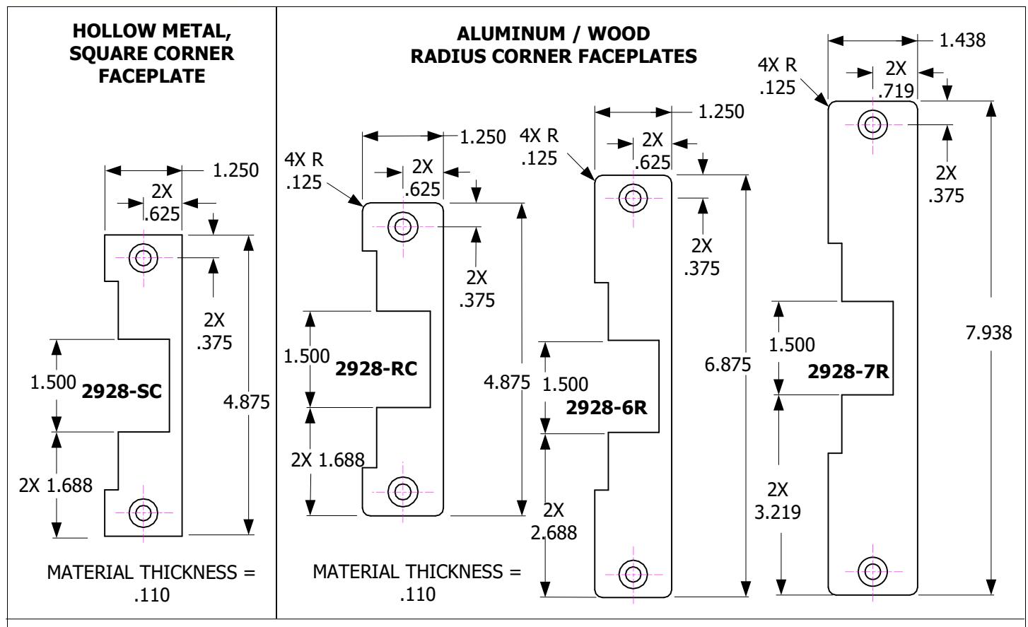
2928-SC 4.875" (124mm) Square corners for wood and hollow metal frames.
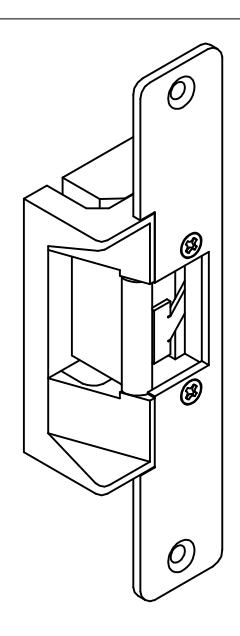
- 2928-RC 4.875" Radius corners for aluminum/ wood frame
- 2928-6R 6.875" Radius corners for aluminum/ wood frame.
- 2928-7R 7.938" Radius corners for aluminum/ wood frame
FEATURES:
- For 5/8" latch or 3/4" latch with 1/8" door gap.
- Latch bolt monitor standard.
- Keeper closed & deadlocked standard.
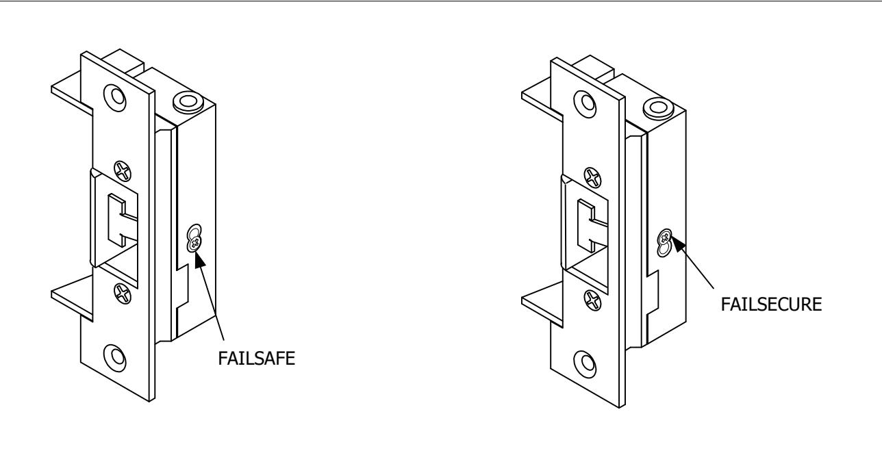
- Field selectable fail-safe / fail-secure.
- Field selectable voltage, 12/24V AC/DC
- AC with Rectifier (BR64XL)
- 1/4" horizontal alignment adjustment.
- Plug-in wire connectors.
- Low profile, 1-3/16" deep
- All stainless steel parts with durable die cast body for corrosion resistance.
- Fewer moving parts for maximum life.
- 630 stainless steel standard.
-
ANSI A156.31
- UL Listed (BP10254)

FAILSECURE STANDARD. FIELD ADJUSTABLE FROM FAILSECURE TO FAILSAFE AS SHOWN
Green -

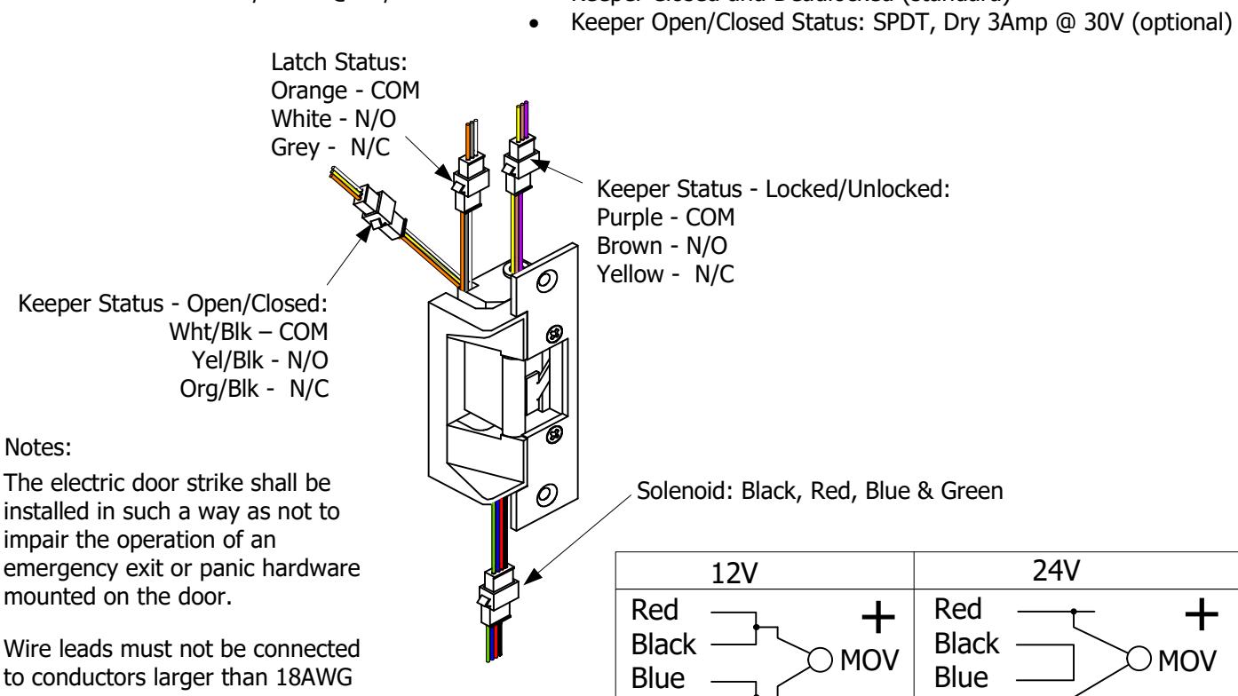
ELECTRICAL DATA:
MONITORING:
- Dual Voltage: 200/100mA @ 12/24VDC 140/70mA @ 12/24VAC
- Latch Status: SDPT, dry 3Amp @ 30V (standard)
- Keeper Closed and Deadlocked (standard)
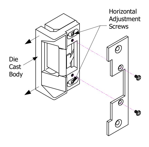
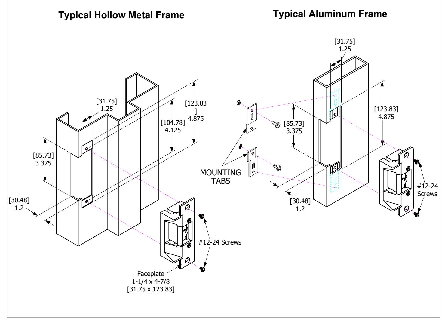
Horizontal Adjustment
Green
Remove Faceplate. Loosen Horizontal Adjustment Screws and slide Die Cast Body out as needed. Retighten Adjustment Screws and replace Faceplate.