2600 Floor Mount Single Side Electromagnetic Holder – Installation Template
Open the original PDF document
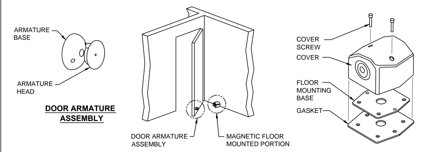
View PDF2600 ELECTROMAGNETIC DOOR HOLDER, SINGLE FLOOR MOUNT
FRONT VIEW
2600 MAGNETIC FLOOR MOUNTING PORTION
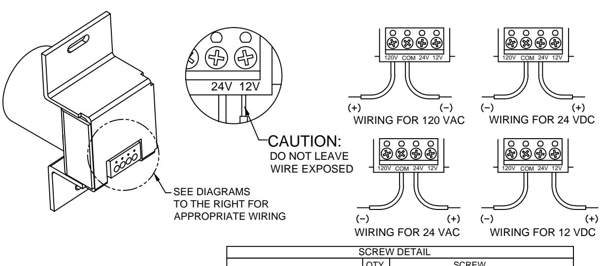
ELECTRICAL DATA:
THIS PRODUCT IS AN ELECTROMAGNETIC HOLDING DEVICE, INTENDED FOR USE IN FIRE DOOR APPLICATIONS, BUT CAN BE USED FOR OTHER MAGNETIC APPLICATIONS. WIRE INTO PROPER TERMINALS AS NOTED BELOW:
| SERIES | VOLTAGE | DC/mA | DC/VA | AC/mA | AC/VA | TERMINALS |
|---|---|---|---|---|---|---|
| 2600 | 12 DC | 60 | .72 | Com & 12 v | ||
| 24 AC/DC | 30 | .72 | 30 | .72 | Com & 24 v | |
| 120 AC | 30 | 3.60 | Com & 120 v |
| QTY | SCREW | |-----------------------------------
® www.abhmfg.com E-mail: abhinfo@abhmfg.com Architectural Builders Hardware Mfg., Inc. 1222 Ardmore Ave., Itasca, IL 60143 630.875.9900; FAX 800.9FAXABH (932.9224)
ABH is a minority owned and operated manufacturing company.
2600
2600-1-03.DWG
© 2015 ABH Mfg., Inc. printed in USA
PAGE 1 OF 2 REVISED 07-13-15
2600 ELECTROMAGNETIC DOOR HOLDER, SINGLE FLOOR MOUNT
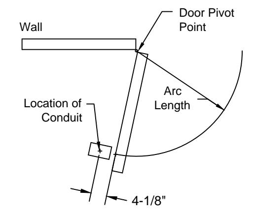
FLOOR MAGNET LOCATION
- 1. Find the following:
- a. Pivot point of door
- b. Door Width
- Maximum degree of door opening permitted by door opener. (Note: trim and partition clearance needed)
- Determine arc length by subtracting 5-5/8" from width of door. Example :
Door width 36"-5-5/8" = 30-3/8" (Arc length)
3. Determine degree of desired door opening with consideration for partition. Allow 6" dia. clearance around conduit and any partition for 2600 series Assembly (see drawing to the right) (Conduit should be located on THE arc and 4-1/8" from the pull side of door, when the door is at the maximum degree of door opening)
FLOOR MAGNET INSTALLATION:
- Locate magnet assembly on pull side of door near bottom rail. Approximately 6" from lock edge using floor mounting base as template.
- 2. Using marked locations, drill mounting holes in floor for 5/8" floor anchors.
- 3. Mount gasket and magnet base to floor using 5/8" anchors and screws.
- For electrical wiring detail, consult " ELECTRICAL DATA" on page 1.
IMPORTANT : Check that power voltage equals one of the voltages labeled on back of magnet.
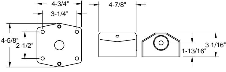
Floor Mounting Base
Floor Magnet Assembly
5. Assemble cover to base plate using provided mounting screws.
DOOR ARMATURE INSTALLATION:
- 1. With the magnet box securely fastened, aligned and energized, place and center the door armature on the surface of the magnet with the two holes of the base aligned either vertically or horizontally.
- 2. Gently close the door and adjust the angle of the door armature so the base lays flat against the door.
- 3. While keeping slight pressure on the door,mark location of door armature through the two base holes. The two marks should be 1-3/4" apart and the center line of the door armature should be approximately 6" from the lock edge of the door.
- 4. Drill through the door where the two marks are located with 5/16" drill. Fasten armature with the (2)10-32 machine screws & sex bolts provided.
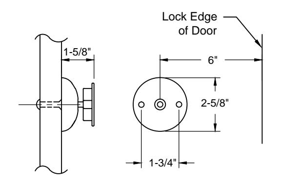
NOTE: All dimensions are provided in inches, unless noted otherwise.

www.abhmfg.com E-mail: abhinfo@abhmfg.com Architectural Builders Hardware Mfg., Inc. 1222 Ardmore Ave., Itasca, IL 60143 630.875.9900; FAX 800.9FAXABH (932.9224)
ABH is a minority owned and operated manufacturing company.
2600
2600-2-03 DWG
© 2015 ABH Mfg., Inc. printed in USA
PAGE 2 OF 2 REVISED 07-13-15