2500 Series Installation Instruction – I-LS00889-Rev2
Open the original PDF document
View PDF


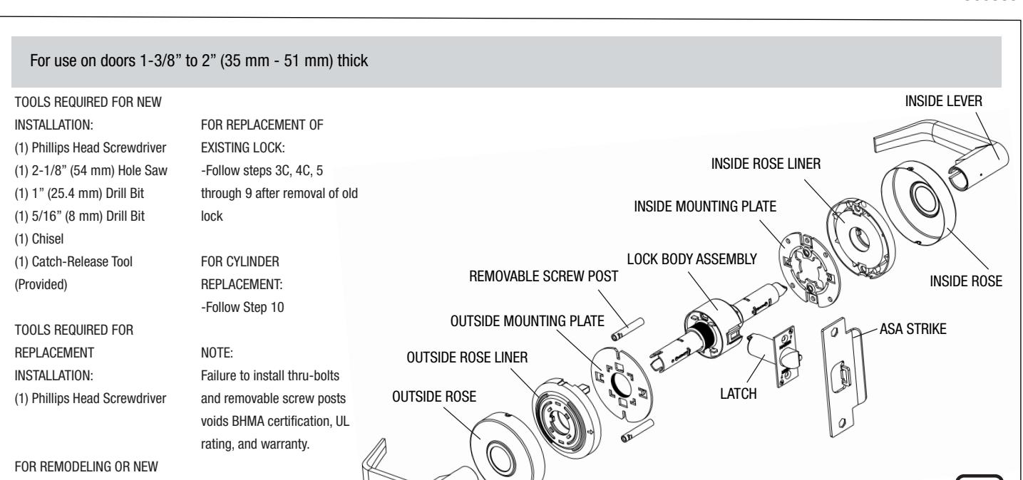
OUTSIDE LEVER
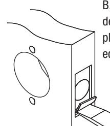
1. MARK DOOR
CONSTRUCTION: -Follow all steps
CENTER LINE MARK FOR 2-1/8" (54 mm) HOLE ON DOOR FACE MARK FOR 1" (25.4 mm) HOLE IN DOOR EDGE
Measure center line of lock; height as desired from finished floor. Select 2-3/4" or optional 2-3/8" backset, fold and apply template to high side of door bevel and mark center of door edge as indicated on template. Mark center hole and screwpost holes on door face through guide on template.
2. DRILL HOLES
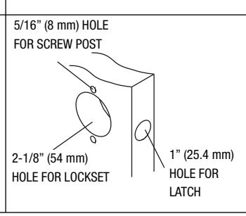
Drill 2-1/8" (54 mm) hole through door face as marked for lockset. (It is recommended that holes be drilled from both sides on wood doors to prevent splitting.) Drill 5/16" (8 mm) holes for screwposts. Drill 1" (25.4 mm) hole in center of door edge for latch.
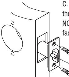
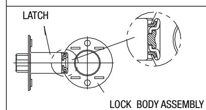
3. INSTALL LATCH
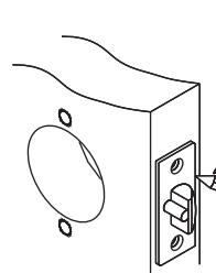
A. Insert latch in hole keeping it parallel to face of door. Mark outline of latch face plate and
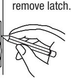
B. Chisel 5/32" (4 mm) deep or until latch face plate is flush with door edge.
(ILLUSTRATION: ENTRANCE FUNCTION)
C. Insert latch and tighten to the door using #8 screws. NOTE: Latchbolt bevel must face to closing direction.
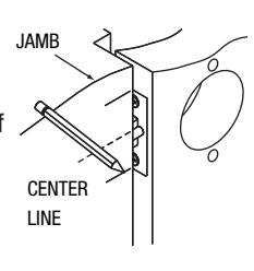
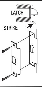
4. INSTALL STRIKE
A. Close door until latchbolt touches jamb. Locate strike in jamb and center line of strike. Open door and extend line to door stop. Measure one half of door thickness plus 1/8" from door stop. Vertically mark center line for strike.
B. Drill two (2) 1" (25.4 mm) holes 3/4" (19 mm) deep in door jambs 5/16" (8 mm) above and 5/16" (8 mm) below horizontal center line. CAUTION: To ensure proper lockset function, hole in jamb must be drilled a full 3/4" (19 mm) deep.
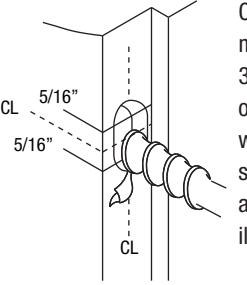
C. Cut out jamb mortise for strike 3/32" (2.4 mm) deep or until strike is flush with jamb. Tighten screws. Latch stops against strike, as illustrated.
REV 2 - 11/30/16 Page 1 of 2

2500 Series ANSI Grade 2 Lever Set Installation Instructions Meets ANSI 156.2 I-LS00889
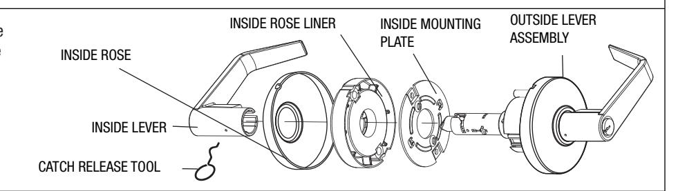
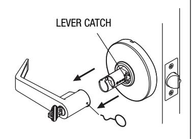
5. REMOVE INSIDE TRIM
Use catch release tool to depress lever catch visible under hole of inside lever shank and slide off inside lever, rose, rose liner, and mounting plate.
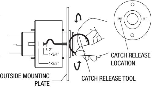
6. ADJUST DOOR THICKNESS
A. Outside mounting plate is pre-set for 1-3/4" door thickness. To fit different door thicknesses, remove outside lever, rose, and rose liner. Now adjust the outside mounting plate by rotating plate until tip of catch release tool lines up with desired door thickness indicated on lock body assembly.
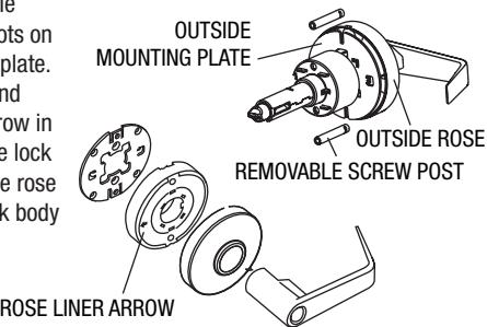
B. Install removable screw post into slots on outside mounting plate. Install rose liner and align rose liner arrow in the direction of the lock stile. Install outside rose and lever onto lock body assembly.
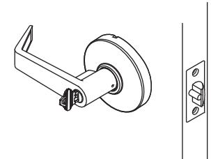
7. INSTALL OUTSIDE LEVER ASSEMBLY
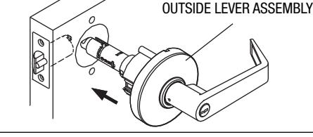
Install outside lever assembly on the door. Make sure tail of latch engages with retractor correctly as illustrated.
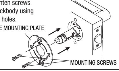
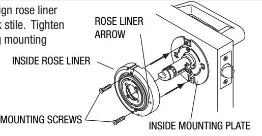
8. INSTALL INSIDE MOUNTING PLATE AND ROSE LINER
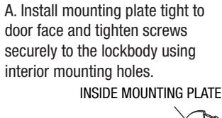
B. Install inside rose liner and align rose liner arrow in the direction of the lock stile. Tighten rose liner to the thru posts using mounting screws.
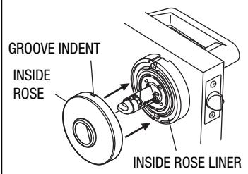
A. Align indent on inside rose with groove on inside rose liner. Press inside rose onto inside rose liner and rotate clockwise to fully seat inside rose.
B. Push lever all the way in until it clicks into catch hole.
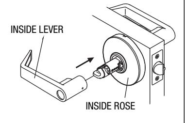
9. INSTALL INSIDE ROSE AND LEVER 10. REPLACE CYLINDER (SKIP THIS STEP IF INSTALLING 3510 OR 3540)

A. Turn key clockwise 1/4 turn. B. Using catch release tool, press the lever catch and pull the lever off.
REV 2 - 11/30/16 Page 2 of 2