2300 Electromagnetic Door Holder 180 Degree Opening Template
Open the original PDF document
View PDF2300 ELECTROMAGNETIC DOOR HOLDER, 180°, SURFACE WALL MOUNT
WALL PORTION INSTALLATION:
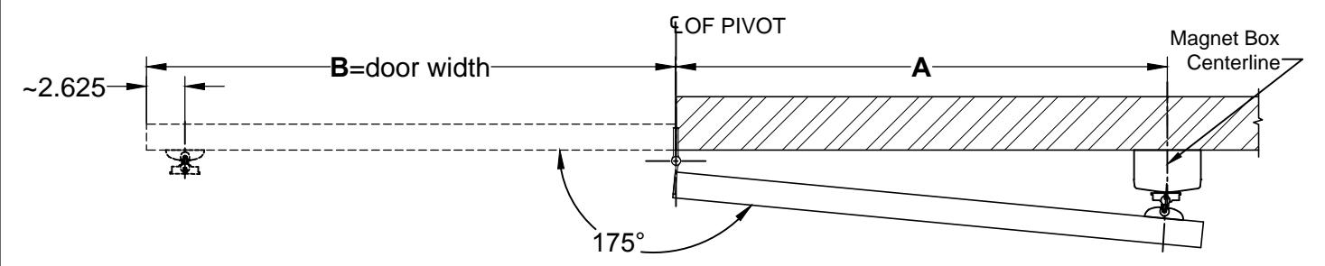
- 1. Measure distance from pivot centerline to Magnet Box centerline (Dim. "A").
- 2. Determine door width (Dim. "B").
-
3. Use table below to locate magnet box centerline on wall .
- a. Example: Dim. "B" = 36" Result Dim. "A" = 33-5/16".
- b. If Dim. "B" falls between dimensions listed in the table below, allow for difference.
Example: Dim. "B" = 40" Then Dim. "A" = 37-5/16".
- 4. Suggested vertical location is on top rail approximately 5" from top of the door.
- 5. Check degree of door opening and coordinate with door closer and other door hardware.
- 6. Total projection of door hardware must not be more than 5-5/8" on the pull side of door. If greater, you will need to use additional extensions, sold separately
| DIM. "B" (NOM. DOOR WIDTH) - 180° | |||||||
|---|---|---|---|---|---|---|---|
| 24" | 28" | 30" | 32 | 36 | 42 | 48 | |
| DIM "A" | 21-5/16" | 25-5/16" | 27-5/16" | 29-5/16" | 33-5/16" | 39-5/16" | 45-5/16" |
- 7. From centerline of pivot, measure the appropriate Dim. "A" in step 3.
- 8. Proper electrical wire routing must be done before installing magnet box.
- 9. The electrical box should be installed with reinforcement to withstand a minimum 50lb. pull.
IMPORTANT : Check that power voltage equals voltage labeled on back of magnet. Refer " ELECTRICAL DATA" on page 1.
DOOR ARMATURE INSTALLATION:
- 1. Place and center the door armature on the surface of the magnet with the two holes of the base aligned horizontally.
- 2. Gently close the door and adjust the angle of the door armature so the base lays flat against the door.
- 3. While keeping slight pressure on the door, mark location of door armature through the two base holes.
- 4. Drill through the door where the two marks are located with 5/16" drill. Fasten with the (2)10-32 machine screws & sex bolts provided.
NOTE: 1. All dimensions are provided in inches, unless noted otherwise.
2. Additional extensions can be ordered separately to increase the door armature projection: 3/8", 1/2", 3/4", 1", 2", 4" or 6".
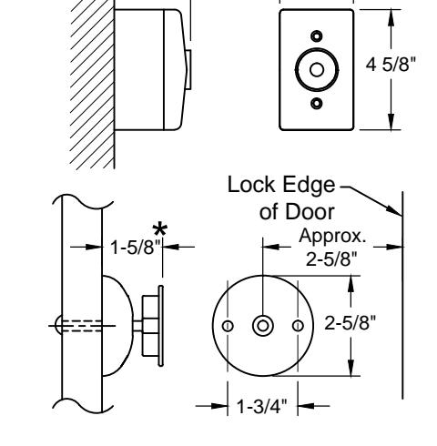
★ For 2-5/8" Door Projection, ☐ 1" → Use 1" Extension provided Complimentry 1" Extension
ST-5357 DWG
E-mail: abhinfo Architectural Buil 1222 Ardmore Ave. 630.875.9900; FAX
www.abhmfg.com E-mail: abhinfo@abhmfg.com Architectural Builders Hardware Mfg., Inc. 1222 Ardmore Ave., Itasca, IL 60143 630.875.9900; FAX 800.9FAXABH (932.9224)
© 2019 ABH Mfg., Inc. printed in USA
ST-5357
ISSUED 04-11-19