2100T Electromagnetic Door Holder with Internal Timer, Recessed, Wall Mount – Template
Open the original PDF document
View PDF2100T ELECTROMAGNETIC DOOR HOLDER WITH INTERNAL TIMER, RECESSED, WALL MOUNT

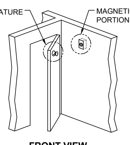
FRONT VIEW
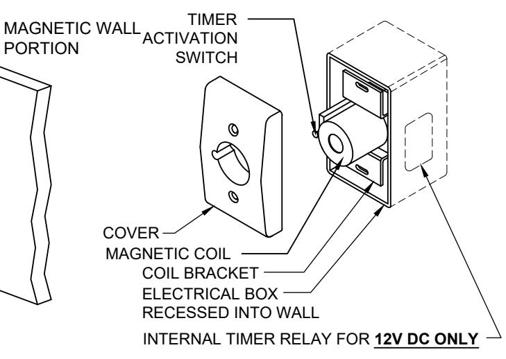
2100T MAGNETIC WALL PORTION
ELECTRICAL DATA:
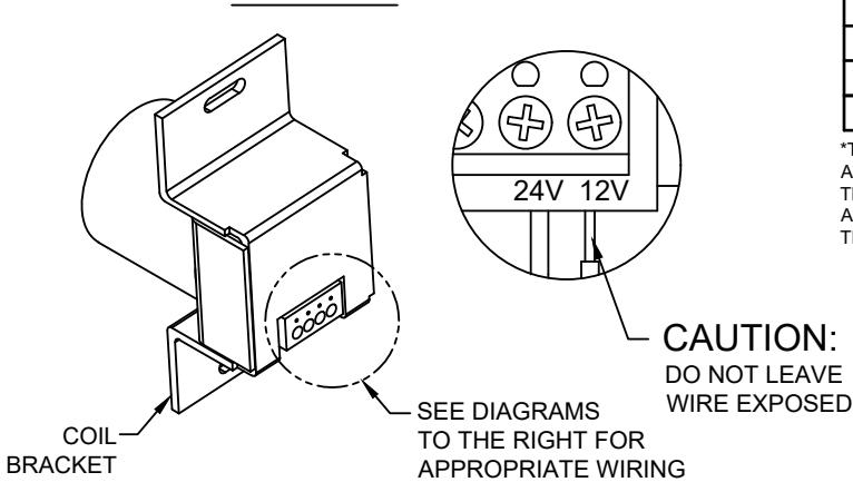
THIS PRODUCT IS AN ELECTROMAGNETIC HOLDING DEVICE, INTENDED FOR USE IN FIRE DOOR APPLICATIONS, BUT CAN BE USED FOR OTHER MAGNETIC APPLICATIONS. WIRE INTO PROPER TERMINALS AS NOTED BELOW:
| 2100T SERIES SPECIFICATIONS | |
|---|---|
| VOLTAGE: | 12 DC |
| DC/ma | 60 |
| DC/VA | .72 |
| TERMINALS | Com & 12 v |
| TIMER RELAY SPECIFICATIONS | |
|---|---|
| VOLTAGE RANGE: | 5v-20v |
| MAX CURRENT: | 5amp or 10amp |
| *FACTORY PRESET TIME DURATION: | 3 minutes |
| TIMER CURRENT CONSUMPTION: | 0.004amp |
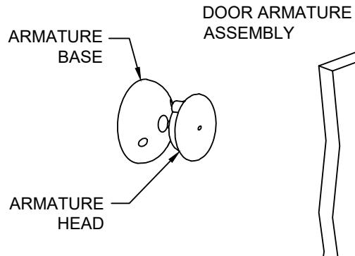
*TIMER IS PRESET TO HOLD DOORS OPEN FOR 3 MINUTES FROM THE TIME OF ACTIVATION. ACTIVATION IS ACHIEVED WHEN THE DOOR IS OPENED ALLOWING THE DOOR ARMATURE PLATE TO CONTACT THE WALL MAGNET, PUSHING THE ACTIVATION SWITCH. DOOR WILL AUTOMATICALLY RELEASE AFTER THE SET TIME PERIOD.
RELAY
MAGNET
DOOR———————————————————————————————————
TOP VIEW
| SCREW DETAIL | |||||||||
|---|---|---|---|---|---|---|---|---|---|
| QTY | SCREW | ||||||||
| MAGNETIC WALL PORTION | 2 | 6-32 x 1" OVAL HEAD MACHINE SCREW | |||||||
| MAGNETIC COVER | 2 | 6-32 x 1" FLAT HEAD MACHINE SCREW | |||||||
| DOOR ARMATURE | 2 | 10-32 x 1" PAN HEAD MACHINE SCREW | |||||||
| | CONTRACTOR | | - | 10-32 x 1-1/4" SNB | |||||||
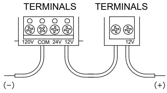
WIRING FOR 12 VDC WITH INTERNAL TIMER RELAY
2100T-1-01.DWG
MANUFACTURING INC.
www.abhmfg.com E-mail: abhinfo@abhmfg.com Architectural Builders Hardware Mfg., Inc. 1222 Ardmore Ave., Itasca, IL 60143 630.875.9900; FAX 800.9FAXABH (932.9224)
© 2022 ABH Mfg., Inc. printed in USA
PAGE 1 OF 2 REVISED 01-17-22
21001
2100T ELECTROMAGNETIC DOOR HOLDER WITH INTERNAL TIMER, RECESSED, WALL MOUNT
WALL PORTION INSTALLATION:
- 1. Measure distance from pivot centerline to wall (Dim. "A").
- 2. Determine door width (Dim. "B").
-
3. Use table below to locate magnet box on wall (Dim. "C").
- a. Example: Dim. "A" = 10" Dim. "B" = 42" Result Dim. "C" = 38-7/8".
-
b. If Dim. "A" or Dim. "B" falls between dimensions listed in the table below, allow for difference.
- Example : Dim. "A"= 7" Dim. "B" = 36" Then Dim. "C" = 33-1/8".
- c. If Dim. "A" and Dim. "B" intersect in the shaded area, DO NOT INSTALL magnet box. The degree of door opening will not allow for proper alignment between armature and wall magnet.
- 4. Suggested vertical location is on top rail approximately 5" from top of the door.
- 5. Check degree of door opening shown in table and coordinate with door closer and other door hardware.
- 6. Total projection of door hardware must not be more than 3-5/8" on the pull side of door. If greater, you will need to use additional extensions, sold separately.
| DIM. "B" (DOOR WIDTH) | ||||||||||||||||||||||
|---|---|---|---|---|---|---|---|---|---|---|---|---|---|---|---|---|---|---|---|---|---|---|
| Dim. | | 20 | 30 | 32 | 34 | 36 | 38 | 40 | 42 | 44 | 46 | 48 | |||||||||||
| "A" | Dim"C" | Deg | Dim"C" | Deg | Dim "C" | Deg | Dim "C" | Deg | Dim "C" | Deg | Dim "C" | Deg | Dim"C" | Deg | Dim"C" | Deg | Dim"C" | Deg | Dim "C" | Deg | Dim "C" | Deg |
| 2 | 25-3/8 | 86° | 27-1/8 | 87° | 29-3/8 | 87° | 31-3/8 | 87° | 33-3/8 | 87° | 35-3/8 | 87° | 37-3/8 | 88° | 39-3/8 | 88° | 41-3/8 | 88° | 43-3/8 | 88° | 45-3/8 | 88° |
| 4 | 25-3/8 | 91° | 27-3/8 | 91° | 29-3/8 | 91° | 31-3/8 | 91° | 33-3/8 | 91° | 35-3/8 | 91° | 37-3/8 | 91° | 39-3/8 | 91° | 41-3/8 | 91° | 43-3/8 | 90° | 45-3/8 | 90° |
| 6 | 25-1/4 | 95° | 27-1/4 | 95° | 29-5/8 | 95° | 31-1/4 | 94° | 33-1/4 | 94° | 35-1/4 | 94° | 37-1/4 | 94° | 39-1/4 | 93° | 41-1/4 | 93° | 43-1/4 | 93° | 45-1/4 | 93° |
| 8 | 25 | 100° | 27 | 99° | 29 | 99° | 31 | 98° | 33 | 98° | 35-1/8 | 97° | 37-1/8 | 97° | 39-1/8 | 96° | 41-1/8 | 96° | 43-1/8 | 96° | 45-1/8 | 96° |
| 10 | 24-1/2 | 105° | 26-5/8 | 103° | 28-5/8 | 103° | 30-3/4 | 102° | 33 | 101° | 34-3/4 | 100° | 36-7/8 | 100° | 38-7/8 | 99° | 41 | 99° | 43 | 98° | 45 | 98° |
| 12 | 24 | 109° | 26 | 108° | 28-1/8 | 107° | 30-1/4 | 105° | 32-3/8 | 105° | 34-3/8 | 104° | 36-3/8 | 103° | 38-1/2 | 102° | 40-1/2 | 102° | 42-1/2 | 101° | 44-5/8 | 101° |
| 14 | 23-1/8 | 114° | 24-3/8 | 112° | 27-1/2 | 111° | 29-5/8 | 109° | 31-3/4 | 108° | 33-7/8 | 107° | 35-7/8 | 106° | 38 | 105° | 40 | 105° | 42-1/8 | 104° | 44-1/8 | 103° |
| 16 | 22-1/8 | 119° | 24-3/8 | 117° | 26-5/8 | 115° | 28-7/8 | 113° | 31 | 112° | 33-1/8 | 110° | 35-1/4 | 109° | 37-3/8 | 108° | 39-1/2 | 107° | 41-5/8 | 107° | 43-5/8 | 106° |
| 18 | 24-1/4 | 122° | 25-5/8 | 119° | 27-7/8 | 117° | 30-1/8 | 116° | 32-3/8 | 114° | 34-1/2 | 113° | 36-3/4 | 111° | 38-3/4 | 110° | 41 | 109° | 43 | 108° | ||
| 20 | 26-3/4 | 123° | 29 | 119° | 31-3/8 | 118° | 33-5/8 | 116° | 35-3/4 | 115° | 38 | 113° | 40-1/8 | 112° | 42-3/8 | 111° | ||||||
| 22 | 27-7/8 | 123° | 30-3/8 | 121° | 32-1/2 | 119° | 34-7/8 | 118° | 37 | 116° | 39-1/4 | 115° | 41-1/2 | 114° | ||||||||
| 24 | 31-3/8 | 123° | 33-3/4 | 121° | 36 | 120° | 38-1/4 | 118° | 40-1/2 | 117° | ||||||||||||
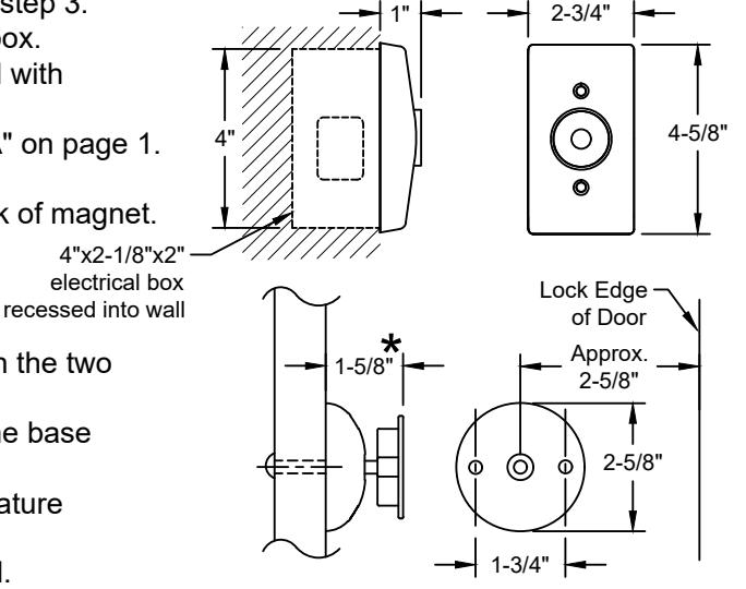
- 7. From corner of wall, measure the appropriate Dim. "C" determined in step 3.
- 8. Proper electrical wire routing must be done before installing magnet box.
- 9. The 4" x 2-1/8" x 2" outlet box ( provided with unit) should be installed with reinforcement to withstand a minimum 50 lb. pull.
- 10. Before installing magnetic wall portion, consult "ELECTRICAL DATA" on page 1.
IMPORTANT : Check that power voltage equals voltage labeled on back of magnet. Consult "ELECTRICAL DATA" on page 1. 4"x2-1/8"x2"
DOOR ARMATURE INSTALLATION:
- 1. Place and center the door armature on the surface of the magnet with the two holes of the base aligned horizontally.
- 2. Gently close the door and adjust the angle of the door armature so the base lays flat against the door.
- 3. While keeping slight pressure on the door, mark location of door armature through the two base holes.
- 4. Drill through the door where the two marks are located with 5/16" drill. Fasten with the (2)10-32 machine screws & sex bolts provided.
NOTE: 1. All dimensions are provided in inches, unless noted otherwise.
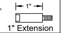
2. Additional extensions can be ordered separately to increase the door armature projection: 3/8", 1/2", 3/4", 1", 2", 4" or 6".
В
Pivot
Centerline
Magnet Box Centerline
★ For 2-5/8" Door Projection, use 1" Extension provided complimentry
2100T-2-01.DWG
2100T

www.abhmfg.com E-mail: abhinfo@abhmfg.com Architectural Builders Hardware Mfg., Inc. 1222 Ardmore Ave., Itasca, IL 60143 630.875.9900; FAX 800.9FAXABH (932.9224)