2-659-0240 Programmable Relay Installation Instructions – I-EA00111-Rev02
Open the original PDF document
View PDF

1. DESCRIPTION
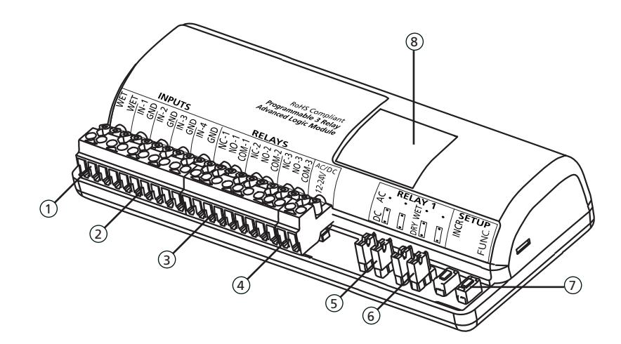
- 1. WET input
- 2. DRY inputs
- 3. Relay outputs
- 4. Power input
- 5. AC/DC jumpers
- 6. WET/DRY jumpers
- 7. Programming buttons
- 8. 7-segment display
2. SPECIFICATIONS
| DESCRIPTION | SPECIFICATION |
|---|---|
| Supply voltage: | 12 – 24 VAC/VDC ±10% |
| Current consumption: | 30 – 130 mA (DRY output) |
| Temperature rating: | -15 – 150 °F (-26 – 150 °C) |
| Input | |
| Input 1, 2, 3, 4: | DRY contact |
| WET input: | 5 – 24 VAC/VDC ±10% |
| Contact rating | |
| Relay 1 (DRY): | 3 A @ 24 VAC or 30 VDC |
| Relay 1 (WET): | 1 A |
| Relay 2: | 3 A @ 24 VAC or 30 VDC |
| Relay 3: | 1 A @ 24 VAC or 30 VDC |
| Dimensions: | 5.2" x 2.2" x 1" (133mm x 55mm x 25mm) |
| Housing: | ABS – white translucent |
3. PRECAUTIONS

- q Shut off all power going to header before attempting any wiring procedures.
- q Maintain a clean & safe environment when working in public areas.
- q Constantly be aware of pedestrian traffic around the door area.
- q Always stop pedestrian traffic through the doorway when performing tests that may result in unexpectedreactions by the door.
- q ESD electrostatic discharge: Circuit boards are vulnerable to damage by electrostatic discharge. Before handling any board ensure you dissipate your body's charge.
- q Always check placement of all wiring before powering up to ensure that moving door parts will not catch any wires and cause damage to equipment.
- q Ensure compliance with all applicable safety standards (i.e. ANSIA156.10/19) upon completion of installation.
-
q DO NOT attempt any internal repair of the sensor. Unauthorized disassembly or repair:
- 1. May jeopardize personal safety and may expose one to the risk of electrical shock.
- 2. May adversely affect the safe and reliable performance of the product will result in a voided productwarranty.
Rev 02, Rev Date: 01/14/2019 Page 1 of 11

4. JUMPERS
PRECAUTIONS TO OBSERVE WHEN USING A 'WET' OUTPUT
Never change the jumper settings when the module has power connected to it or when a load is applied.
Never allow 2 different voltage sources to be connected to the load (electric strike for example) at the same time. This can result in serious damage to equipment.
Always move both jumpers when changing a jumper set.
If an EL device is being powered by a separate power source, DO NOT select the 'WET' output option on the 2- 659-0240. If 'WET' is selected, the next activation of the module will send a voltage to the load and if there is already a voltage being applied from another source, the 2-659-0240 and possibly the load will be permanently damaged.
When using the 'WET' output option on the 2-659-0240, set all desired switch positions ('WET' – 'DRY' and AC – DC) before the module is powered and before any loads are applied.
When DC 'WET' output is selected, COM terminal is positive (+) and the ground (-) is switched between NO and NC.
Ensure there is no other voltage connected to the load. Whatever the Input voltage is at the 2-659-0240, the output will correspond. The following can also be observed:
- 1. If voltage Input at the 2-659-0240 is AC, then output selection can be AC or DC.
- 2. If voltage Input at the 2-659-0240 is DC, then output selection can only be DC.
- 3. The maximum load applied to Relay 1 should never exceed 1A. If more than one device is to be connected, add the consumption values together for a total value. If current is excessive, damage to equipment can result.
- 4. On the 2-659-0240, the 'WET' output is only available at Relay 1.
When supplying 2-659-0240 with AC input voltage and selecting Relay 1 output for 'WET' and DC OUTPUT VOLTAGE, note that the resulting DC output will be the rectified AC input voltage and therefore, about 40% higher than the AC input voltage (rms).
CAUTION: Relay 1 'WET' OPTION IS ACTIVE FOR ALL FUNCTIONS!
| RELAY 1 OUTPUT | DRY/WET JUMPER2 | AC OUTPUT VOLTAGE3 | DC OUTPUT VOLTAGE4 |
|---|---|---|---|
| DRY | both jumpers set to DRY | N/A | N/A |
| WET1 | both jumpers set to WET | both jumpers set to AC | both jumpers set to DC |
NOTES:
- 1. "WET output" allows the 2-659-0240 to supply a voltage output of up to 1 A on relay 1 for powering maglocks or electric strikes directly from the 2-659-0240. Rating of power supply which powers the 2-659-0240must be at least 1 A.
- 2. Default jumper settings make relay 1 DRY.
- 3. AC voltage only available if 2-659-0240is powered by AC voltage.
- 4. DC voltage available if 2-659-0240is powered by AC or DC voltage.
5. WIRING
Each 2-659-0240 function is wired differently. Please review and follow the appropriate wiring diagram shown for each function.
Rev 02, Rev Date: 01/14/2019 Page 2 of 11

6. FUNCTIONS & PARAMETERS
| FUNCTION | DESCRIPTION | LOGIC |
|---|---|---|
| 10 | timer |
activation of relay 1 via trigger of input 1
reverse logic available |
| 11 | ratchet / latching | ratchet/latching of relay 1 via trigger of input 1 |
| 22 |
2-relay sequencer
+ inhibitor |
sequence of relay 1 and relay 2 with inhibiting of input 1 until input 2, input 3, or WET
input is triggered activation of input 4 reinhibits input 1 |
| 28 |
2-relay sequencer
+ door position |
sequence of relay 1 and relay 2 via trigger of input 1 or WET input
input 2 allows delay to run when open but not when closed |
| 29 | deactivation timer |
sequence of relay 1 and relay 2 via trigger of input 1 or WET input
input 2, once opened after sequence, allows relay 1 to deactivate input 2 allows delay to run when open but not when closed input 3 disables sequence, reverse logic available |
| 36 |
3-relay sequencer
+ '1-shot' |
sequence of relay 1 and relay 2 and relay 3 via trigger of input 1 or WET input
relay 1, relay 2, and relay 3 can be maintained or '1-shot' |
| 37 |
3-relay sequence with
'independent relay' |
sequence of relay 1 and relay 2 and relay 3 via trigger of input 1 or WET input
relay 1, relay 2, and relay 3 can be 'independent' or sequenced |
| 50 | interlock timer | interlock of relay 1 and relay 2 via trigger of input 1 and input 2, respectively |
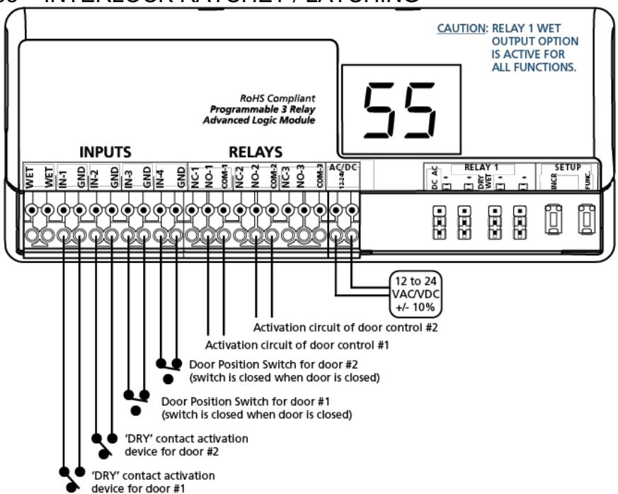
| 55 | interlock ratchet / latching | interlock ratchet of relay 1 and relay 2 via trigger of input 1 and input 2, respectively |
| 65 | 2-way 2-relay sequence |
sequence of relay 1 and relay 2 via trigger of input 1
sequence of relay 2 and relay 1 via trigger of input 2 input 3 triggers relay 1 individually, input 4 triggers relay 2 individually |
| nL | normally locked restroom |
sequence of relay 1 (lock), relay 2 (door), and relay 3 (occupied indicators) for normally
locked, single occupancy restrooms |
| nU | normally unlocked restroom |
sequence of relay 1 (lock), relay 2 (door), and relay 3 (occupied indicators) for normally
unlocked, single occupancy restrooms |
| dn |
3-relay sequencer +
'day / night mode' |
sequence of relay 1 and relay 2 and relay 3 via trigger of input 1 or WET input
input 2 operation dependent upon input 4 ('day / night mode') |
| 00 | disable |
2-659-0240 disabled
00 is the default setting and has no assigned function |
| PARAMETER | DESCRIPTION | LOGIC | |
|---|---|---|---|
| h1 | relay 1 hold time |
00 – 60 seconds
countdown begins AFTER release of input 1 or WET input |
|
| h2 | relay 2 hold time |
00 – 60 seconds
countdown begins AFTER d1 (delay between relay 1 & relay 2) expires |
|
| h3 | relay 3 hold time |
00 – 60 seconds
countdown begins AFTER d2 (delay between relay 1 & relay 3) expires |
|
| d1 |
delay between
relay 1 & relay 2 |
00 – 60, _1 (1/4), _2 (1/2), _3 (3/4) seconds
delay begins AT activation of input 1 or WET input |
|
| d2 |
delay between
relay 1 & relay 3 |
00 – 60, _1 (1/4), _2 (1/2), _3 (3/4) seconds
delay begins AT activation of input 1 or WET input |
|
| rL | reverse logic |
00 = normal logic
input 1 trigger must be NO and close its contact to trigger |
01 = reverse logic
input 1 trigger must be NC and open its contact to trigger |
| nP | no parameters | no parameters available for selected function | |
Rev 02, Rev Date: 01/14/2019 Page 3 of 11

7. PROGRAMMING
- 1. Press and hold INCR + FUNC for 3 seconds. The display will toggle between FF and 00 for 5 seconds.1,2
- 2. While FF and 00 is displayed, press INCR to cycle through functions.3
- 3. Once the desired function is selected, press FUNC to cycle through the parameters. The display will toggle between the parameter and its current value for 5 seconds.
- 4. Press INCR to cycle through the parameter's values.4
- 5. Repeat steps 4 7 until all function parameters are set.
- 6. Wait 5 seconds for the 2-659-0240 to save and display the function.
NOTES:
- 1. Function 00 disables the 2-659-0240.
- 2. "nP" = no parameters are applicable for the selected function.
- 3. Relay hold time(s) and delay time(s) MUST be set for any relay that is to be utilized. Ex: For function 36, if using only relay 1, h1 must be set… if using relay 1 and relay 2, h1, h2, and d1 must be set.
- 4. Pressing and holding INCR will rapid cycle.
8. PROGRAMMING PARAMETERS
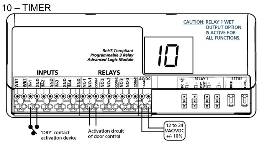
AVAILABLE PARAMETERS:
h1 – relay 1 hold time
rL – reverse logic
• Trigger INPUT 1. Relay 1 will close and hold for time h1.
NOTES:
Reverse logic allows for a Normally Closed (NC) INPUT 1.
11 – RATCHET / LATCHING
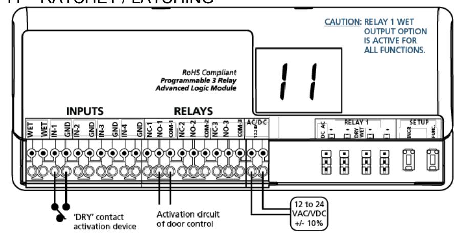
AVAILABLE PARAMETERS:
None
- Trigger INPUT 1. Relay 1 will close and hold indefinitely.
- Trigger INPUT 1. Relay 1 will open.
Rev 02, Rev Date: 01/14/2019 Page 4 of 11

22 – 2-RELAY SEQUENCER + INHIBITOR
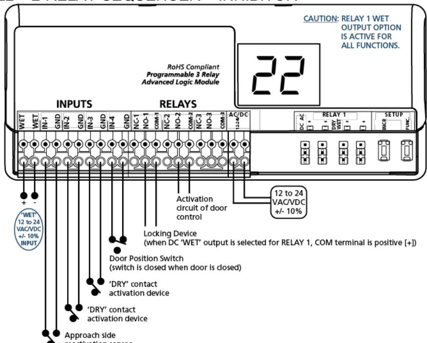
AVAILABLE PARAMETERS:
h1 – relay 1 hold time (must be greater than d1 when using an electric lock)
h2 – relay 2 hold time
d1 – delay between relays 1 and 2
• Trigger INPUT 2, 3, or WET. Relay 1 will close and hold for time h1. Relay 2 will close after time delay d1 and hold for time h2.
NOTES:
Ensure INPUT 1 does not initiate the sequence and that INPUT 4 is closed when the door is closed.
28 – 2-RELAY SEQUENCER + DOOR POSITION
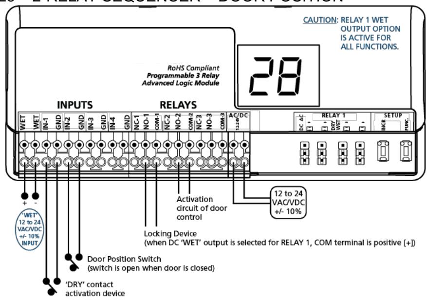
AVAILABLE PARAMETERS:
h1 – relay 1 hold time (must be greater than d1 when using an electric lock)
h2 – relay 2 hold time
d1 – delay between relays 1 and 2
• Trigger INPUT 1 or WET. Relay 1 will close and hold for time h1. Relay 2 will close after time delay d1 and hold for time h2.
NOTES:
INPUT 2 allows the delay to run when the contact is open but triggers RELAY 2 immediately when the contact is closed.
Rev 02, Rev Date: 01/14/2019 Page 5 of 11

29 – DEACTIVATION TIMER
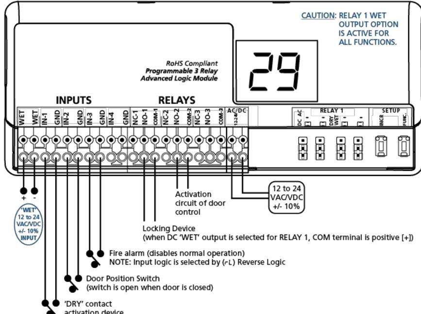
AVAILABLE PARAMETERS:
h1 – relay 1 hold time (must be greater than d1 when using an electric lock)
h2 – relay 2 hold time
d1 – delay between relays 1 and 2
rL – reverse logic
• Trigger INPUT 1 or WET. Relay 1 will close and hold for time h1. Relay 2 will close after time delay d1 and hold for time h2.
NOTES:
INPUT 2 deactivates RELAY 1 once INPUT 2 is opened (and after the sequence has run). INPUT 2 allows the delay to run when the contact is open, but triggers RELAY 2 immediately when the contact is closed. INPUT 3 disables the sequence.
36 – 3-RELAY SEQUENCER + "1-SHOT"
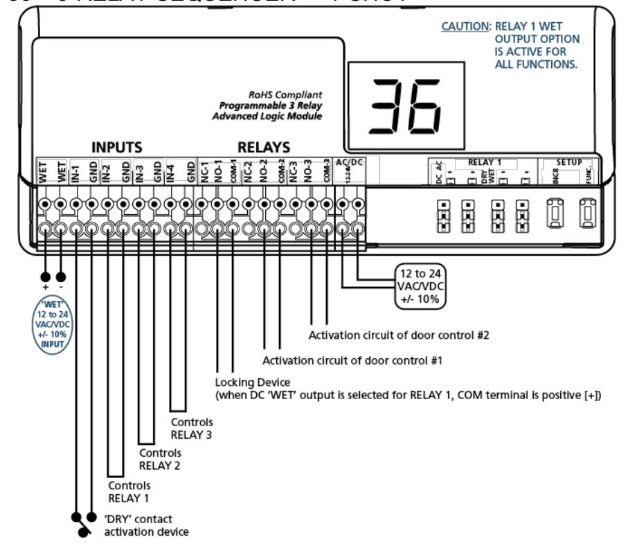
AVAILABLE PARAMETERS:
h1 – relay 1 hold time (must be greater than d1 when using an electric lock)
h2 – relay 2 hold time
h3 – relay 3 hold time
d1 – delay between relays 1 and 2
d2 – delay between relays 1 and 3
• Trigger INPUT 1 or WET. Relay 1 will close and hold for time h1. Relay 2 will close after time delay d1 and hold for time h2. Relay 3 will close after time delay d2 and hold for time h3.
NOTES:
If INPUT 1 or 'WET' is maintained, jumping INPUT 2, 3, and/or 4 will allow RELAY 1, 2, and/or 3 (respectively) to close, run the hold time and then open. If no jumpers are set, RELAYS 1, 2, and/or 3 will close, hold and not time out (open, i.e. 1-shot) until INPUT 1 or 'WET' is released.
Rev 02, Rev Date: 01/14/2019 Page 6 of 11

37 – 3-RELAY SEQUENCER WITH "INDEPENDENT RELAY"
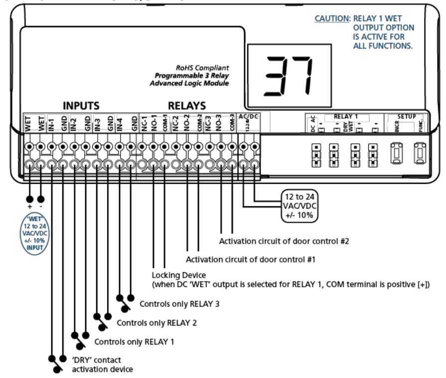
AVAILABLE PARAMETERS:
h1 – relay 1 hold time (must be greater than d1 when using an electric lock)
h2 – relay 2 hold time
h3 – relay 3 hold time
d1 – delay between relays 1 and 2
d2 – delay between relays 1 and 3
- Trigger INPUT 1 or WET. Relay 1 will close and hold for time h1. Relay 2 will close after time delay d1 and hold for time h2. Relay 3 will close after time delay d2 and hold for time h3.
- Trigger INPUT 2. Relay 1 will close and hold for time h1.
- Trigger INPUT 3. Relay 2 will close and hold for time h2.
- Trigger INPUT 4. Relay 3 will close and hold for time h3.
50 – INTERLOCK TIMER
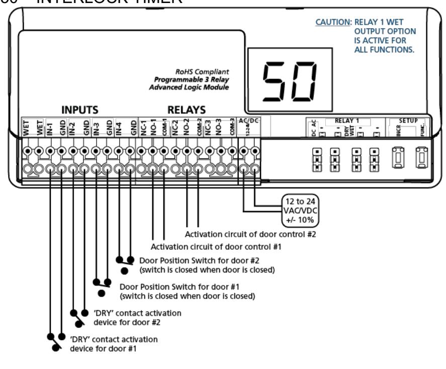
AVAILABLE PARAMETERS:
h1 – relay 1 hold time h2 – relay 2 hold time
- Trigger INPUT 1. Relay 1 will close and hold for time h1.
- Trigger INPUT 2. Relay 2 will close and hold for time h2.
NOTES:
If INPUT 1 is triggered, INPUT 2 and RELAY 2 will be inhibited until INPUT 3 (door position switch) is closed. Conversely, if INPUT 2 is triggered, INPUT 1 and RELAY 1 will be inhibited until INPUT 4 (door position switch) is closed.
Rev 02, Rev Date: 01/14/2019 Page 7 of 11

55 – INTERLOCK RATCHET / LATCHING
AVAILABLE PARAMETERS:
None
- Trigger INPUT 1. Relay 1 will close and hold indefinitely.
- Trigger INPUT 1. Relay 1 will open.
- Trigger INPUT 2. Relay 2 will close and hold indefinitely.
- Trigger INPUT 2. Relay 2 will open.
NOTES:
If INPUT 1 is triggered, INPUT 2 and RELAY 2 will be inhibited until INPUT 3 (door position switch) is closed. Conversely, if INPUT 2 is triggered, INPUT 1 and RELAY 1 will be inhibited until INPUT 4 (door position switch) is closed.
65 – 2-WAY, 2-RELAY SEQUENCE
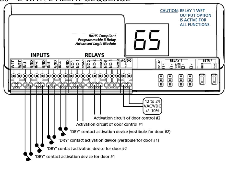
AVAILABLE PARAMETERS:
h1 – relay 1 hold time
h2 – relay 2 hold time
d1 – delay between relays 1 and 2
d2 – delay between relays 2 and 1
- Trigger INPUT 1. Relay 1 will close and hold for time h1. Relay 2 will close after time delay d1 and hold for time h2.
- Trigger INPUT 2. Relay 2 will close and hold for time h2. Relay 1 will close after time delay d2 and hold for time h1.
- Trigger INPUT 3. Relay 1 will close and hold for time h1.
- Trigger INPUT 4. Relay 2 will close and hold for time h2.
Rev 02, Rev Date: 01/14/2019 Page 8 of 11

nL – NORMALLY LOCKED RESTROOM
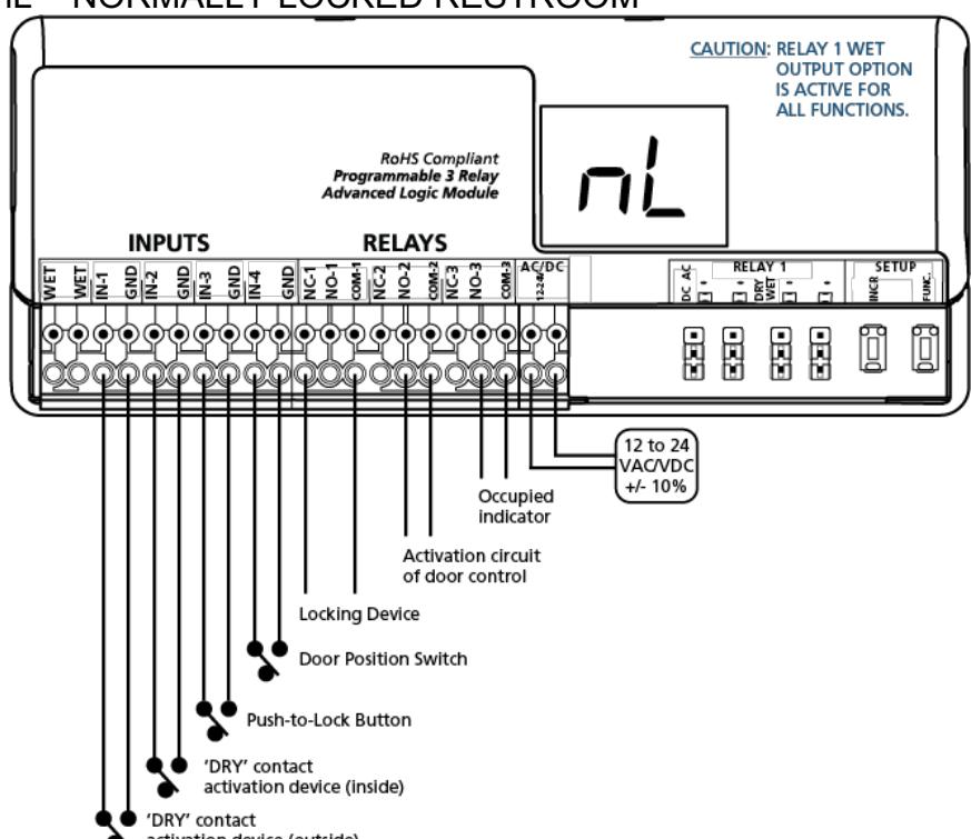
AVAILABLE PARAMETERS:
h1 – relay 1 hold time (h1 must be greater than d1)
h2 – relay 2 hold time
d1 – delay between relays 1 and 2
- Trigger INPUT 1. Relay 1 will close and hold for time h1. Relay 2 will close after time delay d1 and hold for time h2.
- Trigger INPUT 3. Relay 3 will close and INPUT 1 will be inhibited.
- Trigger INPUT 2. Relay 1 will close and hold for time h1. Relay 2 will close after time delay d1 and hold for time h2. Relay 3 will open.
NOTES:
INPUT 3 will not function unless INPUT 4 is closed. INPUT 4 should be closed when the door is closed.
nU – NORMALLY UNLOCKED RESTROOM
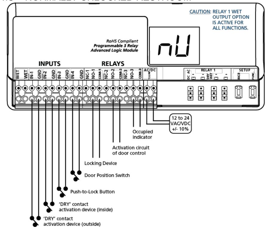
AVAILABLE PARAMETERS:
h2 – relay 2 hold time
d1 – delay between relays 1 and 2
- Trigger INPUT 1. Relay 2 will close and hold for time h2.
- Trigger INPUT 3. Relay 1 and 3 will close and INPUT 1 will be inhibited.
- Trigger INPUT 2. Relay 1 will open. Relay 2 will close after time delay d1 and hold for time h2. Relay 3 will open.
NOTES:
INPUT 3 will not function unless INPUT 4 is closed. INPUT 4 should be closed when the door is closed.
Rev 02, Rev Date: 01/14/2019 Page 9 of 11

dn – 3-RELAY SEQUENCE WITH "DAY / NIGHT MODE"
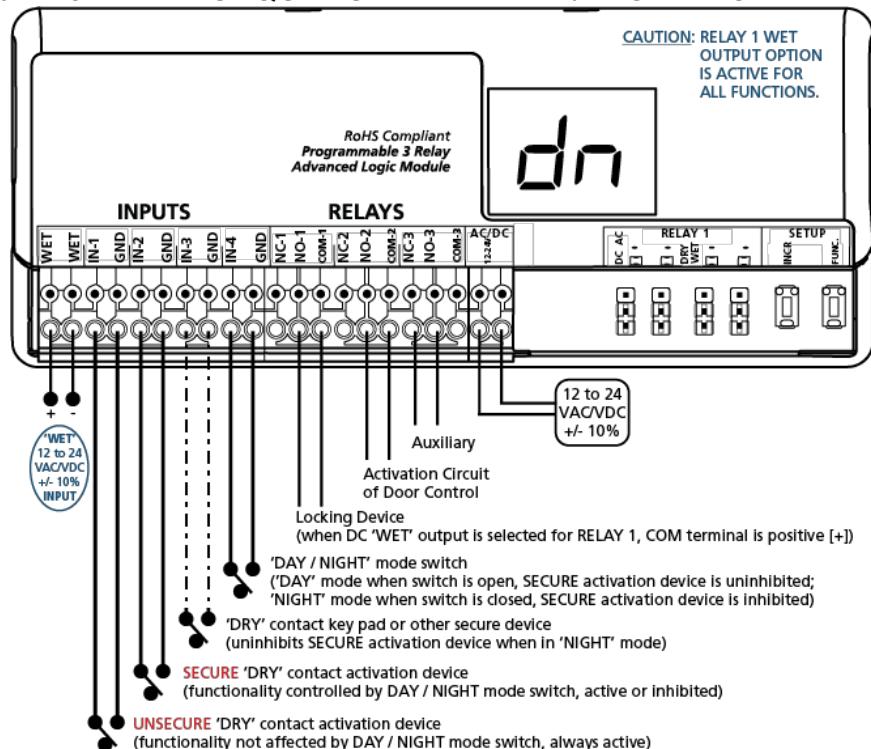
AVAILABLE PARAMETERS:
h1 – relay 1 hold time
h2 – relay 2 hold time
h3 – relay 3 hold time
d1 – delay between relays 1 and 2
d2 – delay between relays 1 and 3
- Trigger INPUT 1, INPUT2, or WET. Relay 1 will close and hold for time h1. Relay 2 will close after time delay d1 and hold for time h2. Relay 3 will close after time delay d2 and hold for time h3.
- Trigger INPUT 3. Relay 1 will close and hold for time h1. INPUT 2 will be uninhibited for 5 seconds.
NOTES:
INPUT 2 will only function if INPUT 4 is open.
9. TEST
Upon completion of jumper settings, wiring, and programming, test the 2-659-0240 to ensure that all function parameters are working correctly and as intended for the specific application.
10. RELAY STATUS
| STATUS | DESCRIPTION |
|---|---|
| r1 | relay 1 closed when wired NO or open when wired NC |
| r2 | relay 2 closed when wired NO or open when wired NC |
| r3 | relay 3 closed when wired NO or open when wired NC |
| r= | relay 1 and relay 2 closed when wired NO or open when wired NC |
| r= | relay 1 and relay 3 closed when wired NO or open when wired NC |
| rº | relay 1, relay 2, and relay 3 closed when wired NO or open when wired NC |
Rev 02, Rev Date: 01/14/2019 Page 10 of 11

11. FUNCTION CROSS-REFERENCE
|
Rev 0
FUNCTION |
REV 1
FUNCTION |
|---|---|
| 21 | 22 |
| 25 | 28, 29, 36, or 37 |
| 35 | 36 or 37 |
| 75 | 28, 29, 36, or 37 |
12. TROUBLESHOOTING
| PROBLEM | POSSIBLE CAUSE | CORRECTIVE ACTION |
|---|---|---|
| 2-659-0240 will not react to any inputs | Incorrect power |
Verify power supply of 12 to 24 VAC/VDC +/-
10% is wired to correct terminals. |
| Not programmed |
Ensure a function is programmed, 2-659-0240
does not show 00, and all 'H' values are set to at least 01. |
|
| Incorrect wiring |
Verify wiring is applied exactly as described
for specific function programmed. |
|
| Defective 2-659-0240 | Replace 2-659-0240. | |
| 2-659-0240 has no output | Incorrect output devices |
Ensure proper devices are connected to
outputs for the specific function programmed. |
| Not programmed |
Ensure a function is programmed, 2-659-0240
does not show 00, and all 'H' values are set to at least 01. |
|
| Incorrect wiring |
Verify wiring is applied exactly as described
for specific function programmed. |
|
| Incorrect jumper settings |
Ensure all jumpers are configured correctly
for specific application. |
|
| Defective 2-659-0240 | Replace 2-659-0240. | |
| 2-659-0240 output is constant/maintained |
One or more of IN-1 through IN-4 have
shorted |
Resolve respective short. |
| E1, E2, E3, E4, E5 | EEPROM error | Reset 2-659-0240 and reprogram. |
INSTALLATION/SERVICE COMPLIANCE EXPECTATIONS
The sensor manufacturer cannot be held responsible for incorrect installations or inappropriate adjustments of the sensor/device; therefore, the sensor manufacturer does not guarantee any use of the sensor outside of its intended purpose.
The sensor manufacturer strongly recommends that installation and service technicians be AAADM-certified for pedestrian doors, IDA-certified for doors/gates, and factory-trained for the type of door/gate system.
Installers and service personnel are responsible for executing a risk assessment following each installation/service performed, ensuring that the sensor system installation is compliant with local, national, and international regulations, codes, and standards.
Once installation or service work is complete, a safety inspection of the door/gate shall be performed per the door/gate manufacturer recommendations and/or per AAADM/ANSI/DASMA guidelines (where applicable) for best industry practices. Safety inspections must be performed during each service call – examples of these safety inspections can be found on an AAADM safety information label (e.g. ANSI/DASMA 102, ANSI/DASMA 107, UL 325).