1800_Series_Installation_Instructions
Open the original PDF document
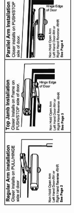
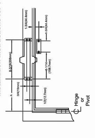
View PDFInstallation Instructions for PARALLEL ARM (PUSH SIDE) Mounting
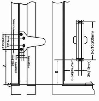
Size 2, Size 3
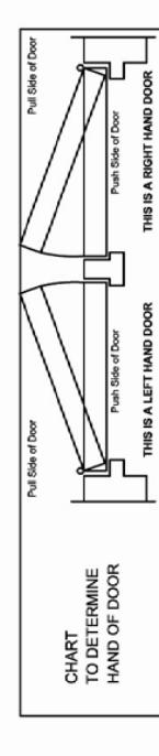
Left hand door shown Right hand door shown Dimensions are in inches Do not scale drawing
INSTALLATION INSTRUCTONS
1. Select door opening and use dimensions shown above, mark four (4) hake on frame door and two (5) hakes on door of an anthon. 2. Drill plot hokes in door door and two (5) hakes on door of an anthon. 2. Drill plot hokes in door and farme for if 14 all-juryobe screws or did to up for 14.4.5. meeting screws provided. 3. Intall forearmerm since assembly to door uning screws provided. 4. About closes of man using acress provided. 4. About closes of man are using acress provided. 4. About C MUST RE POSITIONED TOWARD HINGE EDGE. 5. Intall main am two top prinor and the proportious for farme when assembled to preload main am (illustration below). Secure forearm to main arm with screws whather assembled to preload main and (illustration below). Secure forearm to main arm with acress whather assembled to provided main arm (illustration below). Secure forearm is man with acress whether assembled to provided main arm (illustration below). Secure forearm to main arm with acress whether assembled to provided main arm of main arm with acress whether assembled to provided main arm to main arm with acress whether assembled provided. 7. Seno princin specific specific or following instructions as shown pager 1.
Size: 4&5
OPENING BUINA BUINA DIMA DIMAR DIMAR DIMAR DIMAR DIMAR DIMAR DIMAR DIMAR DIMAR DIMAR DIMAR DIMAR DIMAR DIMAR DIMAR DIMAR DIMAR DIMAR DIMAR DIMAR DIMAR DIMAR DIMAR DIMAR DIMAR DIMAR DIMAR DIMAR DIMAR DIMAR DIMAR DIMAR DIMAR DIMAR DIMAR DIMAR DIMAR DIMAR DIMAR DIMAR DIMAR DIMAR DIMAR DIMAR DIMAR DIMAR DIMAR DIMAR DIMAR DIMAR DIMAR DIMAR DIMAR DIMAR DIMAR DIMAR DIMAR DIMAR DIMAR DIMAR DIMAR DIMAR DIMAR DIMAR DIMAR DIMAR DIMAR DIMAR DIMAR DIMAR DIMAR DIMAR DIMAR DIMAR DIMAR DIMAR DIMAR DIMAR DIMAR DIMAR DIMAR DIMAR DIMAR DIMAR DIMAR DIMAR DIMAR DIMAR DIMAR DIMAR DIMAR DIMAR DIMAR DIMAR DIMAR DIMAR DIMAR DIMAR DIMAR DIMAR DIMAR DIMAR DIMAR DIMAR DIMAR DIMAR DIMAR DIMAR DIMAR DIMAR DIMAR DIMAR DIMAR DIMAR DIMAR DIMAR DIMAR DIMAR DIMAR DIMAR DIMAR DIMAR DIMAR DIMAR DIMAR DIMAR DIMAR DIMAR DIMAR DIMAR DIMAR DIMAR DIMAR DIMAR DIMAR DIMAR DIMAR DIMAR DIMAR DIMAR DIMAR DIMAR DIMAR DIMAR DIMAR DIMAR DIMAR DIMAR DIMAR DIMAR DIMAR DIMAR DIMAR DIMAR DIMAR DIMAR DIMAR DIMAR DIMAR DIMAR DIMAR DIMAR DIMAR DIMAR DIMAR DIMAR DIMAR DIMAR DIMAR DIMAR DIMAR DIMAR DIMAR DIMAR DIMAR DIMAR DIMAR DIMAR DIMAR DIMAR DIMAR DIMAR DIMAR DIMAR DIMAR DIMAR DIMAR DIMAR DIMAR DIMAR DIMAR DIMAR DIMAR DIMAR DIMAR DIMAR DIMAR DIMAR DIMAR DIMAR DIMAR DIMAR DIMAR DIMAR DIMAR DIMAR DIMAR DIMAR DIMAR DIMAR DIMAR DIMAR DIMAR DIMAR DIMAR DIMAR DIMAR DIMAR DIMAR DIMAR DIMAR DIMAR DIMAR DIMAR DIMAR DIMAR DIMAR DIMAR DIMAR DIMAR DIMAR DIMAR DIMAR DIMAR DIMAR DIMAR DIMAR DIMAR DIMAR DIMAR DIMAR DIMAR DIMAR DIMAR DIMAR DIMAR DIMAR DIMAR DIMAR DIMAR DIMAR DIMAR DIMAR DIMAR DIMAR DIMAR DIMAR DIMAR DIMAR DIMAR DIMAR DIMAR DIMAR DIMAR DIMAR DIMAR DIMAR DIMAR DIMAR DIMAR DIMAR DIMAR DIMAR DIMAR DIMAR DIMAR DIMAR DIMAR DIMAR DIMAR DIMAR DIMAR DIMAR DIMAR DIMAR DIMAR DIMAR DIMAR DIMAR DIMAR DIMAR DIMAR DIMAR DIMAR DIMAR DIMAR DIMAR DIMAR DIMAR DIMAR DIMAR DIMAR DIMAR DIMAR DIMAR DIMAR DIMAR DIMAR DIMAR DIMAR DIMAR DIMAR DIMAR DIMAR DIMAR DIMAR DIMAR DIMAR DIMAR DIMAR DIMAR DIMAR DIMAR DIMAR DIMAR DIMAR DIMAR DIMAR DIMAR DIMAR DIMAR DIMAR DIMAR DIMAR DIMAR DIMAR DIMAR
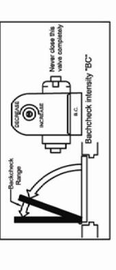
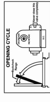
OPEN CYCLE
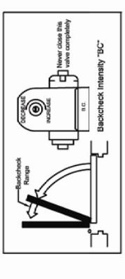
istructions apply to closers equipped with backcheck asse backcheck intensity, turn valve marked "BC"clockese backcheck intensity, turn valve marked BC coun
International* door closers
INSTALLATION INSTRUCTIONS 1800 SERIES DOOR CLOSERS
SIZE2, SIZE3, SIZE 4, SIZE 5, Optional BC, Non-Hold Open
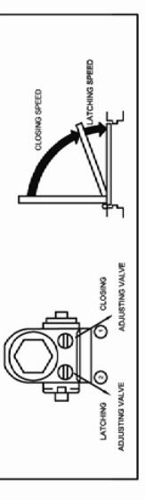
DOOR CLOSER ADJUSTMENT
CLOSING DYCLE. VATE CLOSING accept_CASE and LATCH) are controlled two (2)separate speed adjusting valves adjust the CLOSING speed first, then adjust the LATCHING speed.
1.CLOSING speed adjustment is acomplished by full rotations of the speed adjusting valve. "I'm the speed adjustment valve CLOKKWISE in a SLOWER CLOSE are obtaing speed. -I'm the speed adjustment valve COUNTIECTO.
2. LATCH speed adjustments is accomplished by full rotations of the speed adjusting valve. -Turn the speed adjustment serve CLOKIVISE for a SLOWER LATCHE and chaing speed. -Turn the speed adjustment serve COUNTER-CLOKYWISE for a R-NSTER LATCH are obeing speed.
CAUTIONS
Do not turn speed adjusting valve more than two (2) full turns counter-clockwise from its factory set position as two speed adjusting valves could become disloaged from the door closer body, resulting in the loss of internal fluid and failure of the device.
PAGE 4
PAGE 1
Installation Instructions for REGULAR ARM (PULL SIDE) Mounting
Size 2, Size 3
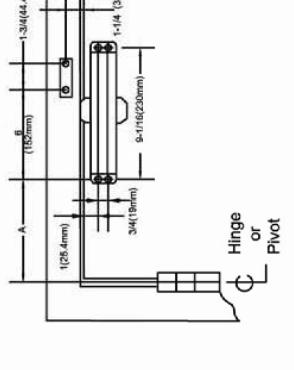
Size: 4&5
Size 2, Size 3
Right hand door shown Left hand door shown Dimensions are in inches Do not scale drawing
| _ | _ | _ |
|---|---|---|
|
DIM.A
Size 485 |
6 (152 mm) | 3-1/2 (89mm) |
|
DIM.A
Size 283 |
6-1/2(165.1mm) | 4(101.6mm) |
| OPENING | To120° | 120°-180° |
OPEN CYCLE
NOTED: Note instructions apply to obsers equipped with backcheck. To increase backcheck intensity, turn valve marked BC counter. To decrease backcheck intensity, turn valve marked BC counter.
1. Select door opening and use dimensions shown above, mark four (4) 1. Select door opening and use of losses on boor of aim show. 2. Drill plot Nobe in door and three for the selection of aim show. 2. Drill plot Nobe in door and three for #1 4 all purpose screws or drill 1. Drill plot Nobe in door and three for #1 4 all purpose screws or drill 3. Intall forearm/arm show assembly to door using screws provided. 3. Intall forearm/arm show assembly to door using screws provided SEEED XALUSTING VALVE MUST BE POSITIONED TOWARDO HINGE EDOGE.
INSTALLATION INSTRUCTONS
Sinstall main arm to be Constituted to the Constitute of Eurose. Sinstall main arm to top pilion shalf, perpendicular to frame when assembled to preload main and multisation below.) Secure forearm to main arm will screwiwasher assembly provided. B Adult engin of forearm so that forearm is perpendicular to frame when assembled to preload main arm (lieutation below). Secure forearm to main arm with acrew washer assembly provided. I stop pilion on one shalf at Doutron of closed. A Supplied colored spate of color. following instructions as shown page 1.
uctions as shown page 1.
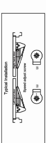
Top View Typical Installation
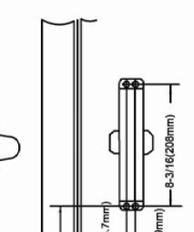
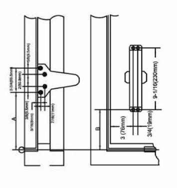
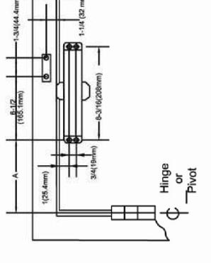
Installation Instructions for TOP JAMB (PUSH SIDE) Mounting
| Į | • | ١ | |
|---|---|---|---|
| ( | 2 | ١ | |
| • | 5 | j | |
| • | • | ||
| ç | ı | ||
| ľ | ١ | Į | |
| Ċ | j | ľ | ١ |
| • | • | ||
C Hinge Pivot
Left hand door shown Right hand door shown Dimensions are in inches Do not scale drawing
| OPENING |
DIM.A
Size 283 |
OIMA
Sab eas |
|---|---|---|
| To120° | 6-1/2(165.1mm) | 6(152 mm) |
| 4000 4000 | 4/101 Smm) | 3-1/2 (80mm) |
OPEN CYCLE
NOTED: These instructions apply to closers equipped with backcheck. To increase backcheck intensity, turn valve marked 'BC'clock' TO decrease beckcheck intensity, turn valve marked BCrountens-clockwise.
1. Select door opening and use dimensions shown above, mark four (4) have on heme door out two (2) They so or door dimensions the solution to the plot house in door and farm for it is all-purpose scrows or drill or by (4.50 maker) has screw. In this for (4.50 maker) has screw. In this forestrained in the or assembly to door using screws provided. A found redoer on from using screws provided Section (4.50 min when the screw of the screws provided or the screws provided. A found redoer on from using screws provided Section (1.50 min or the screws of the screws provided or the screws provided to the screws provided or the screws provided or the screws provided to the screws provided to the screws provided to the screws provided to the screws provided to the screws provided to the screws provided to the screws provided to the screws provided to the screws provided to the screws provided to the screws provided to the screws provided to the screws provided to the screws provided to the screws provided to the screws provided to the screws provided to the screws provided to the screws provided to the screws provided to the screws provided to the screws provided to the screws provided to the screws provided to the screws provided to the screws provided to the screws provided to the screws provided to the screws provided to the screws provided to the screws provided to the screws provided to the screws provided to the screws provided to the screws provided to the screws provided to the screws provided to the screws provided to the screws provided to the screws provided to the screws provided to the screws provided to the screws provided to the screws provided to the screws provided to the screws provided to the screws provided to the screws provided to the screws provided to the screws provided to the screws provided to the screws provided to the screws provided to the screws provided to the screws provided to the screws provided to the screws provided to the screws provided to the screws provided to the screws provi
INSTALLATION INSTRUCTONS
to main arm with screwiwasher assmably provided. Addit length of towerms to the towerm is propriedular to frame when assmabled to prebade main arm (illustration below), Secure forearm to main arm with screw washer assembly provided. T Singo pinion cap over shaft a bottom of closer. 8 Adjust decing speed of door, following instructions as shown page 1.
Top View Typical Installation
PAGE 3