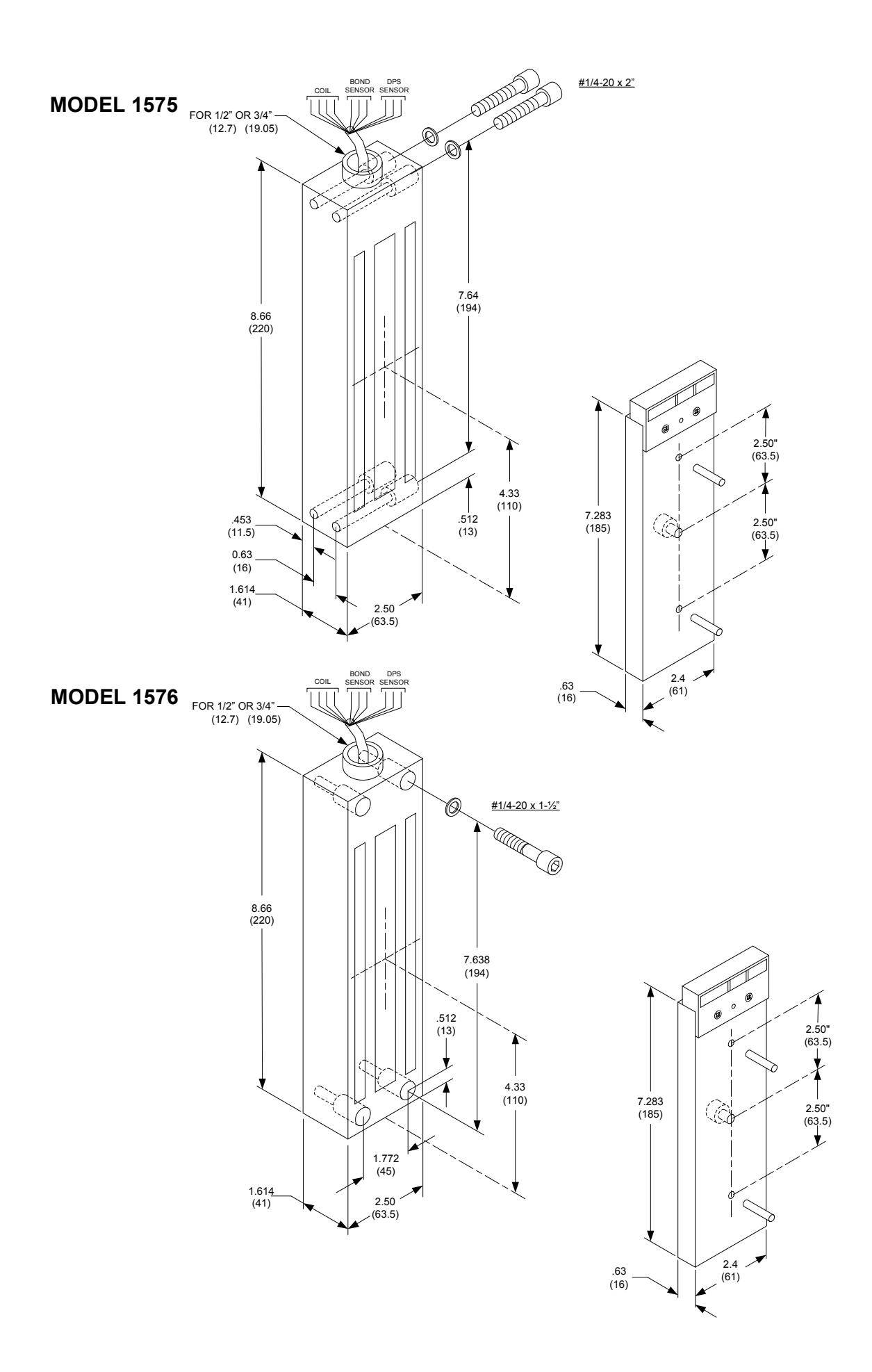
1570 Series 1575-1576 Installation Instructions
Open the original PDF document
View PDF801 Avenida Acaso, Camarillo, ca. 93012 • (805) 494-0622 • Fax: (805) 494-8861 www.sdcsecurity.com • E-mail: service@sdcsecurity.com
1575-1576 EMLOCK INSTALLATION INSTRUCTIONS R
During installation, care must be taken to assure full electro-magnet and armature contact.
The Emlock and armature should be handled carefully. Any damage to the surface such as paint, burrs and dirt will hinder full holding power.
Although all SDC Emlocks are provided with the best possible plating for corrosion resistance, the continued impact of the armature against the Emlock may cause eventual wear of the plating.
If wear causes rust to occur, clean the surface using a fine abrasive pad. Do not use coarse material to clean surfaces.
After cleaning, do not touch the Emlock face or armature with your hands.
A rust inhibitor such as M1 manufactured by Starret, or LPS3 manufactured by LPS Laboratories (available at most hardware stores) may be applied.
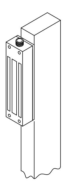
Mount the Emlock to a fence post or similar structure. The armature is mounted to the gate. The fabrication of additional mounting plates and angle brackets may be required by the installer. Due to various gate and fence designs, there is not a standard or recommended method of installation.
Emlocks are fail-safe (locked when energized) devices and require power to remain locked. A power supply with battery backup is required when power outages may interfere with desired security.
INSTALLATION:
- 1. Inspect the gate and post to determine if any mounting plates or angle brackets are required. Install mounting hardware as required.
- 2. Mark the mounting surfaces per the template. Be sure the centerline of the armature template matches the centerline of the Emlock template. Drill and tap holes as indicated.
- 3. Mount the armature to the gate. Determine the proper hardware (provided) see Figure 1. DO NOT SUBSTITUTE ARMATURE MOUNTING HARDWARE AND DO NOT WELD THE ARMATURE DIRECTLY TO THE MOUNTING SURFACE. When properly mounted, the armature will pivot slightly around the mounting screw.
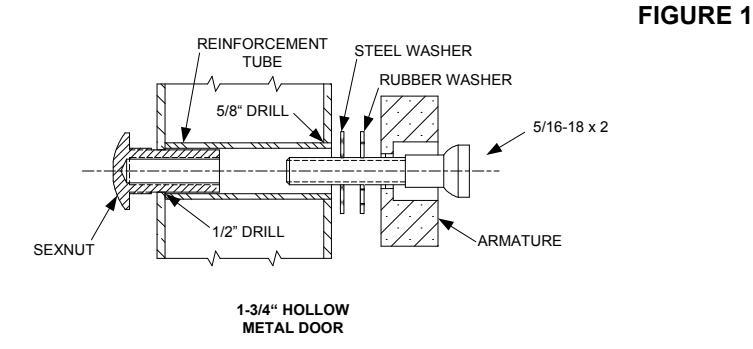
From Sexnut side of door, drill exactly 1/2" hole thru one metal thickness only. From armature side of door, drill 5/8" hole to insert reinforcement tube. Press in sexnut and reinforcement tube all the way and mount armature to door using hardware provided.
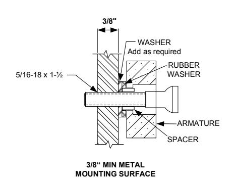
Drill and tape for 5/16 machine screw. Mount armature to door with hardware provided.
INSTALLATION (CONT.):
- 4. Mount the Emlock with hardware provided (See pages 3 & 4).
- 5. Tighten all screws. Install anti-tamper plugs over socket head mounting screws.
- 6. Install 1/2" or 3/4" conduit. A conduit outlet box must be provided within 15" of the lock for wire connections.
- 7. Make all wire connections to a fused power source with the power off.
WIRING DETAILS:
BOND SENSOR (BAS) WIRING
|
WIRE
COLOR |
CONTACT | DESCRIPTION |
|---|---|---|
| YEL | N/O | GOOD BOND |
| GRN | COM | COMMON |
| ORG | N/C | NO/POOR BOND |
DOOR POSITION SENSOR (DPS) WIRING
|
WIRE
COLOR |
CONTACT | DESCRIPTION | |||||
|---|---|---|---|---|---|---|---|
| WHT | N/O | ACTIVATE WHEN DOOR OPEN | |||||
| GRY | COM | COMMON | |||||
| VIO | N/C |
ACTIVATE WHEN DOOR
CLOSED |
|||||
To determine the correct wire gauge to use on a single "circuit" the following information is required:
- 1. The quantity, voltage and current draw of all lock(s) to be connected to the circuit.
- 2. The distance in feet from the power supply to the furthest lock on the circuit.
Add together the current draw (amps) of all locks on the same circuit. Using the AWG Chart below, cross reference the total amps with the distance between the power source and the furthest lock to determine the wire gauge required.
A single "circuit" describes a pair of wires run from the power supply to one or more locks that are wired in parallel. The distance from the power supply to the furthest lock in the "circuit" must not exceed the distance number shown in the chart below and is based on your selected wire gauge. If the distance shown in the chart is inadequate for your application, divide your locks up into 2 or more separate "circuits" and use the chart to check each circuit independently. Fewer locks on each circuit may allow you to use a smaller gauge wire or will allow you to increase the maximum distance between the power supply and the furthest lock on the circuit. More than one circuit can be connected on the same power supply as long as the combined current required from all connected circuits does not exceed the power supply rating.
NOTE: All wiring must be installed in accordance with all state and local codes.
Minimum Wire Gauge For 12 Volts AC or DC
| DIS | TANCE IN | N FEET FR | OM POWE | R SOURC | E TO FAF | RTHEST L | OCKING D | EVICE | |||
|---|---|---|---|---|---|---|---|---|---|---|---|
| AMPS | 25 | 50 | 75 | 100 | 150 | 200 | 250 | 300 | 400 | 500 | 1000 |
| 0.25 | 18 | 18 | 18 | 18 | 18 | 18 | 16 | 16 | 14 | 12 | |
| 0.50 | 18 | 18 | 18 | 18 | 18 | 16 | 16 | 14 | 12 | ||
| 0.75 | 18 | 18 | 16 | 16 | 14 | 14 | 14 | 12 | |||
| 1.00 | 18 | 18 | 16 | 16 | 14 | 12 | |||||
| 1.50 | 18 | 16 | 14 | 14 | 12 | ||||||
| 2.00 | 18 | 16 | 14 | 12 | |||||||
| 2.50 | 18 | 14 | 12 | ||||||||
| 3.00 | 16 | 14 | |||||||||
| 3.50 | 16 | ||||||||||
| DISTANCE IN FEET FROM POWER SOURCE TO FARTHEST LOCKING DEVICE | |||||||||||
Minimum Wire Gauge For 24 Volts AC or DC
| DIS | STANCE IN | N FEET FR | OM POW | ER SOUR | CE TO FAR | THEST L | OCKING E | EVICE | |||
|---|---|---|---|---|---|---|---|---|---|---|---|
| AMPS | 25 | 50 | 75 | 100 | 150 | 200 | 250 | 300 | 400 | 500 | 1000 |
| 0.25 | 18 | 18 | 18 | 18 | 18 | 18 | 18 | 18 | 18 | 16 | 16 |
| 0.50 | 18 | 18 | 18 | 18 | 18 | 18 | 18 | 16 | 16 | 14 | |
| 0.75 | 18 | 18 | 18 | 18 | 18 | 16 | 16 | 16 | 14 | 12 | |
| 1.00 | 18 | 18 | 18 | 18 | 16 | 16 | 14 | 14 | 12 | ||
| 1.50 | 18 | 18 | 18 | 16 | 16 | 14 | 12 | ||||
| 2.00 | 18 | 18 | 18 | 16 | 14 | 14 | 12 | ||||
| 2.50 | 18 | 18 | 16 | 14 | 14 | 12 | |||||
| 3.00 | 18 | 16 | 14 | 14 | 12 | 12 | |||||
| 3.50 | 18 | 16 | 14 | 12 |
1576 GATE EMLOCK® MOUNTING ACCESSORIES
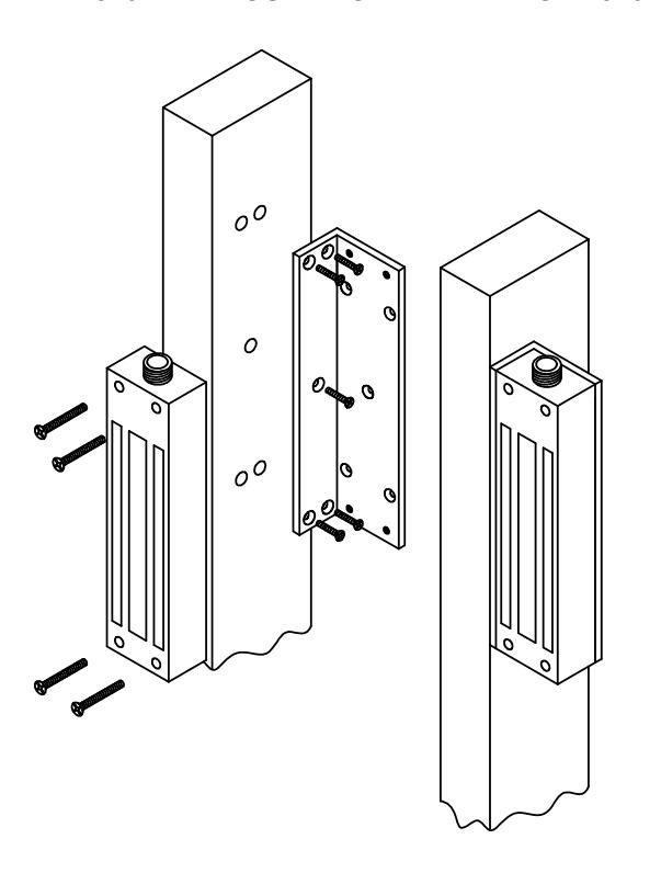
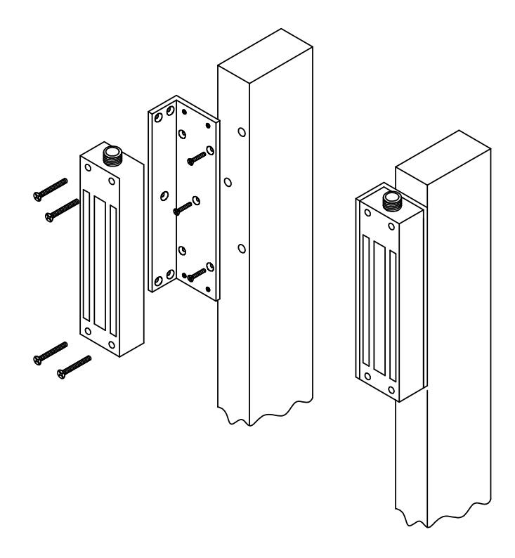
1576-BK – MOUNTING BRACKET FOR 1576
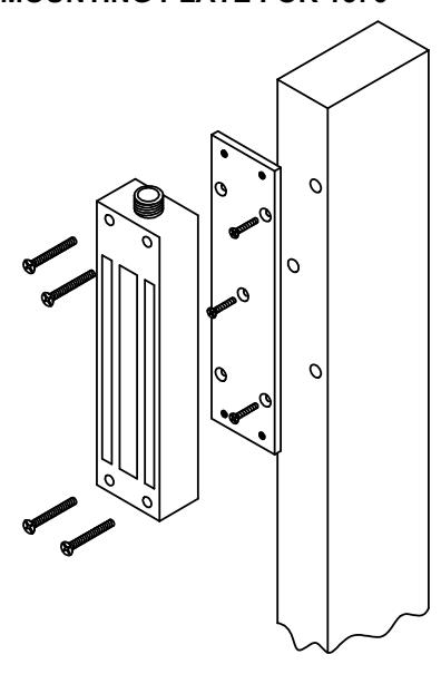
1576-MP – MOUNTING PLATE FOR 1576
TROUBLE SHOOTING 1575-1576 EMLOCK
| PROBLEM | CAUSE | SOLUTION | ||||||
|---|---|---|---|---|---|---|---|---|
|
Residual magnetism.
The lock releases slowly. |
Control switch wired on the
AC side of the power source |
The access control switch must be wired on the DC side of the
power supply. |
||||||
|
When an AC transformer and a bridge rectifier are used, the access
control switch must be wired between the rectifier and the Emlock. |
||||||||
| Poor holding power | Armature installed rigidly. |
The armature must pivot loosely from its center mounting point to
permit full armature contact. |
||||||
| Insufficient voltage |
Check for proper voltage at the Emlock input. If the voltage is low,
determine if the correct wire gauge is being used to prevent excessive voltage drop. |
|||||||
|
Check the power supply load capacity. It must meet or exceed the
combined current rating of the Emlocks on the circuit. |
||||||||
| AC voltage output |
Emlocks require DC input voltage. When an AC trans
former is used, a bridge rectifier must be installed to convert the AC output of the transformer to DC. |
|||||||
|
No magnetic power.
Door does not lock. |
No power |
Check the input voltage at the Emlock. If the voltage is zero or a
low reading, double check all wire connections. |
||||||
| Input polarity reversed. |
Note Polarity:
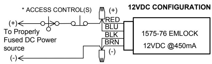
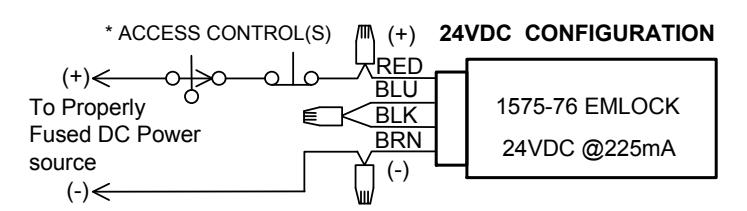
12VDC Config.: RED/BLU – Positive, BRN/BLK – Negative 24VDC Config.: RED – Positive, BRN – Negative |
|||||||
| Open circuit in lock coil. |
Check the Emlock coil continuity with OHM meter. If the reading is
high or open, replace the magnet. |
|||||||
| Coil short. |
A coil short or incorrect wiring will blow fuses. Measure the coil for
correct resistance. If the coil reading is zero or low, replace the magnet. |
|||||||
|
If the coil resistance is correct, check the field wiring for shorts.
Locate and repair the short in the field wiring. |
||||||||
|
BAS Option does not show
lock secure. |
Insufficient voltage |
Check for proper voltage at the Emlock input. If the voltage is low,
determine if the correct wire gauge is being used to prevent excessive voltage drop. |
||||||
|
Armature installed rigidly or
misaligned. |
The armature must pivot loosely from its center mounting point to
permit full armature contact. |
|||||||
|
Surface of magnet or armature
rusted or pitted. |
Clean the armature and surface of the lock (see Page 1) | |||||||