1431 Door Closer With UO-O-RO-O8-OLC-P9-RP9-P3-P3A-P4-P4A-Z-OZA Standard Duty Arms (Without Hold Open) Installation Instructions
Open the original PDF document
View PDF1431 DOOR CLOSER WITH STANDARD DUTY ARMS (WITHOUT HOLD OPEN) INSTALLATION INSTRUCTIONS
1431 SERIES ADJUSTABLE FROM SIZE 1 THRU 6
ASSA ABLOY
FOR INSTALLATION ASSISTANCE, CALL SARGENT AT 1-800-727-5477 • www.sargentlock.com
IMPORTANT NOTICE
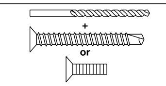
PRE-DRILL 3/32" HOLES FOR SELF-TAPPING SCREWS OR TAP #12-24 FOR MACHINE SCREWS
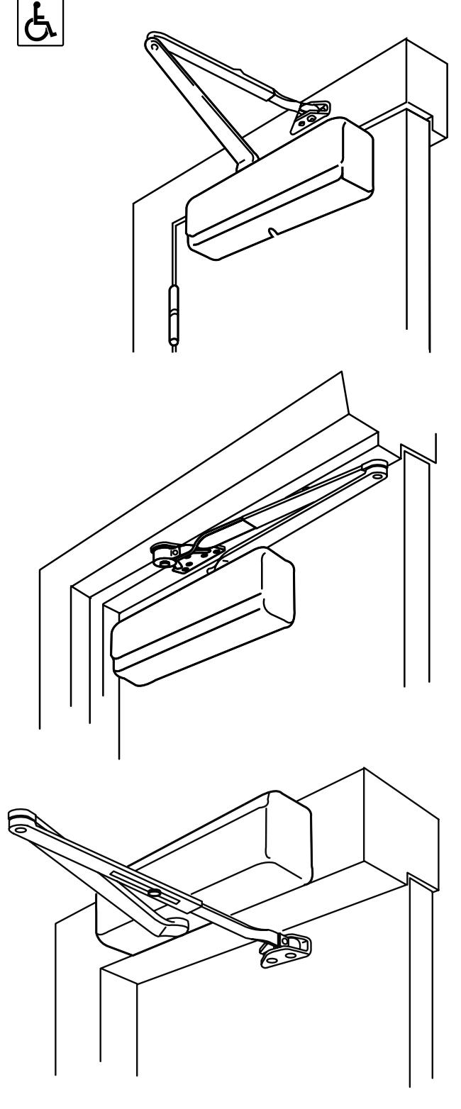
Standard Mounting Application with 0, R0, 08 or 0LC Arm
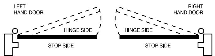
For Standard Applications - Door is mounted on the hinge side of the door (see page 2)
Parallel Arm Application with P9, RP9, P3, P3A, P4 or P4A Arm
For Parallel Arm Applications - Door Closer is mounted on the top side of the door (see page 4)
Top Jamb Application with 0, R0, 0Z or 0ZA Arm
For Top Jamb Application - Door Closer is mounted on the frame on the stop side of the door (see page 6)
STANDARD APPLICATION
- Select closer mounting position based on the maximum door opening, as listed below Note: For ADA applications, select the 160° position.
- 2
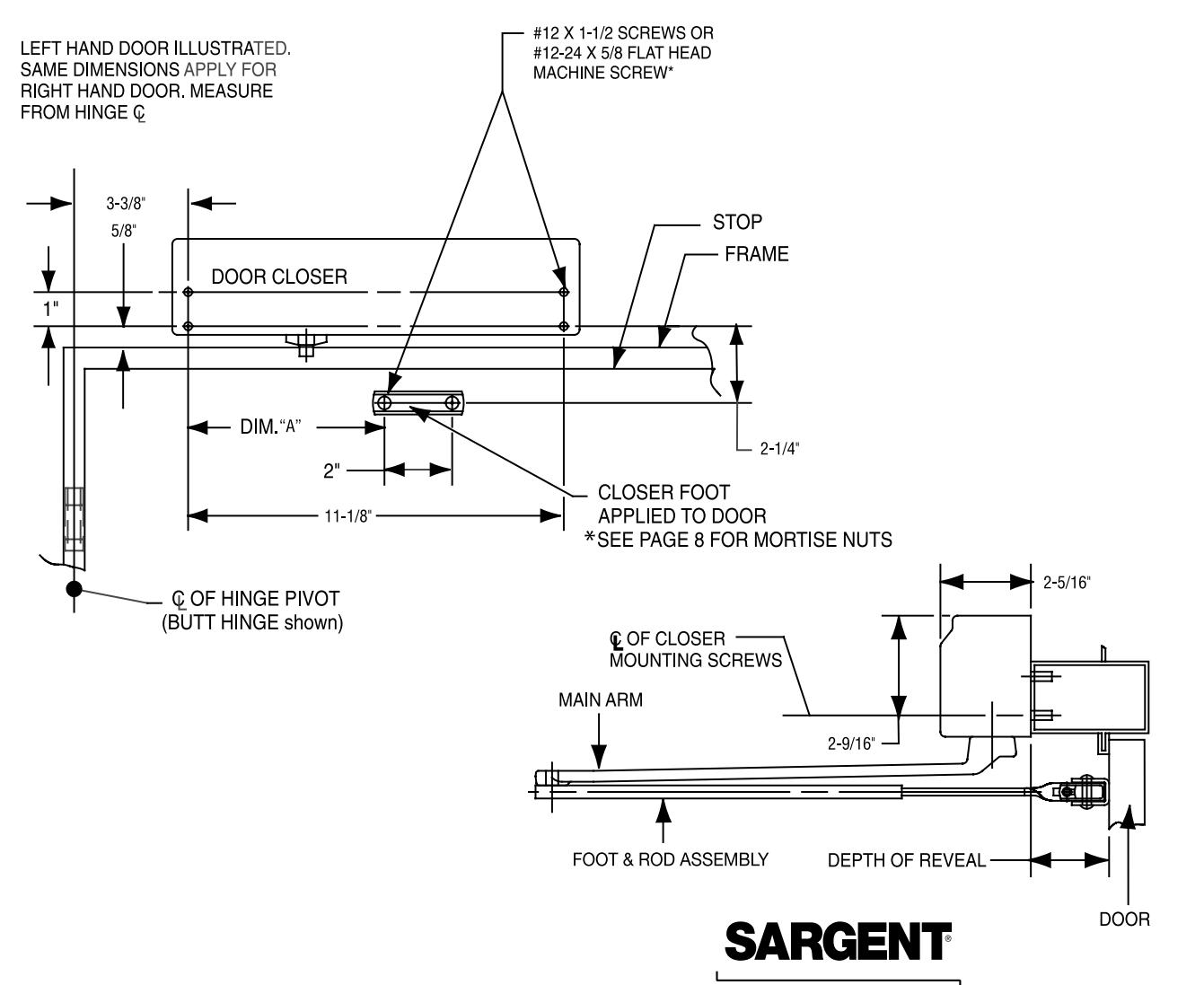
- Using the enclosed self adhesive template, locate and mark hole locations Note: 3/32" pilot holes are required when Self Tapping Screws are being used If machine screws are being used, use a drill #16 (.177) and a #12-24 tap
- 3
- Install closer body onto the door with 5/8" power adjustment nut end away from hinge
- Install foot & rod assembly onto the frames
MAXIMUM DIM. A DIM. B DOOR OPENING 120° 6-3/4" 12-1/8 160°** 4-3/4" 10-1/8"
door will open 180°
**If butt, frame and wall conditions permit,
use the pivot farthest from the hinge
#12 X 1 1/2 SCREWS OR TOP OF DOOR #12-24 X 5/8 FLAT HEAD
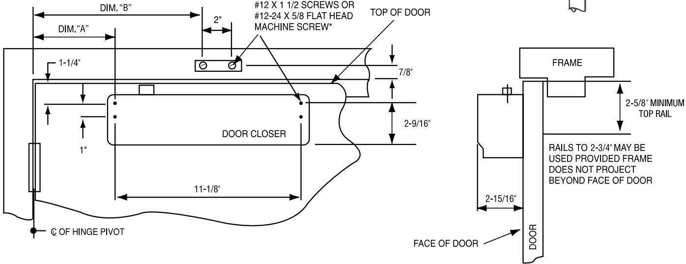
RIGHT HAND DOOR ILLUSTRATED, SAME DIMENSIONS APPLY FOR LEFT HAND DOOR. *SEE PAGE 8 FOR MORTISE NUTS
4
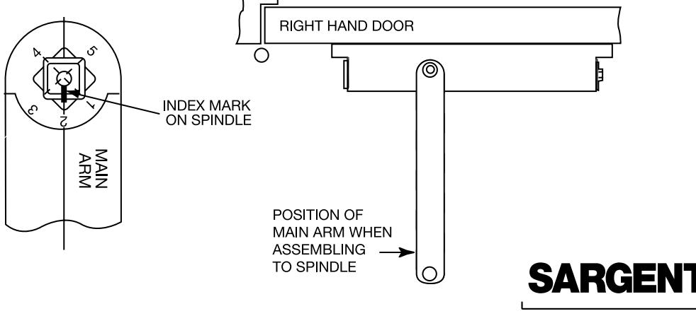
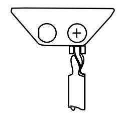
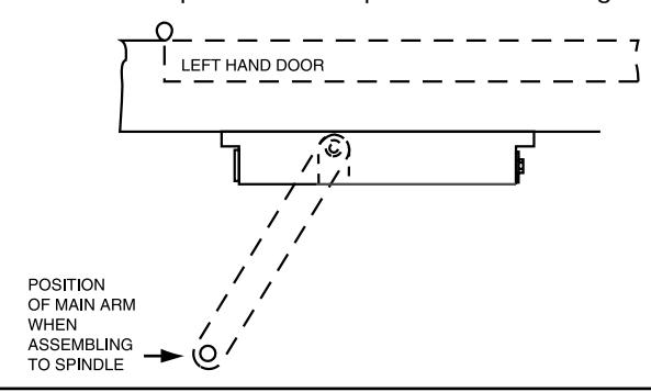
Install main arm on the closer with the index mark on the spindle aligning with #2 on the main arm (as shown)
11/01/11 A7139K
Note: On the foot & rod assembly always
STANDARD APPLICATION
5
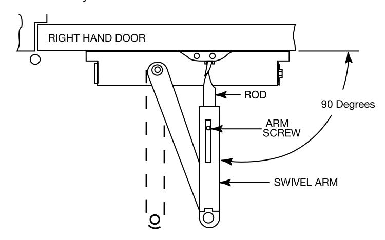
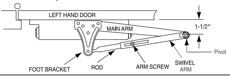
- Opening the door slightly, slide rod into swivel arms and then close the door
- With the door closed, position the swivel arm so it is 90° to the door surface
- Tighten the arm screw securely
6
Adjust closer as required (See page 8 for details)
ACCESSORY INFORMATION
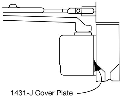
May be used when closer is mounted on a narrow rail to improve appearance when closer is viewed through glass
08 Mortise foot may be used when the standard surface applied foot cannot be attached to the top casing or where appearance is a major
Mortise Foot
factor
1431-W Corner bracket
May be used for exterior doors to keep the closer inside of building; also to obtain full 180° door opening closer is mounted on bracket attached to door jamb on stop side of door
Mortise nuts for bolting through the door are furnished when ordered
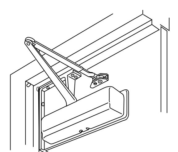
PARALLEL APPLICATION
- Select closer mounting position based on the maximum door opening, as listed below Note: For ADA applications, select the 180° position.
- 2
- Using the enclosed self adhesive template, locate and mark hole locations Note: 3/32" pilot holes are required when Self Tapping Screws are being used If machine screws are being used, use a drill #16 (.177) and a #12-24 tap
- 3
- Install closer body onto the door with 5/8" power adjustment nut end towards hinge
- Install foot bracket & rod assembly onto the frames
|
MAXIMUM
DOOR OPENING |
DIM. A | DIM. B |
|---|---|---|
| 95° | 6-1/2" | 12-3/4" |
| 120° | 4" | 10-1/2" |
| 180° | 1-1/4" | 7-3/4" |
Note: P9 or RP9 arm shown. For P3, P3A, P4,P4A arms, use data sheet enclosed
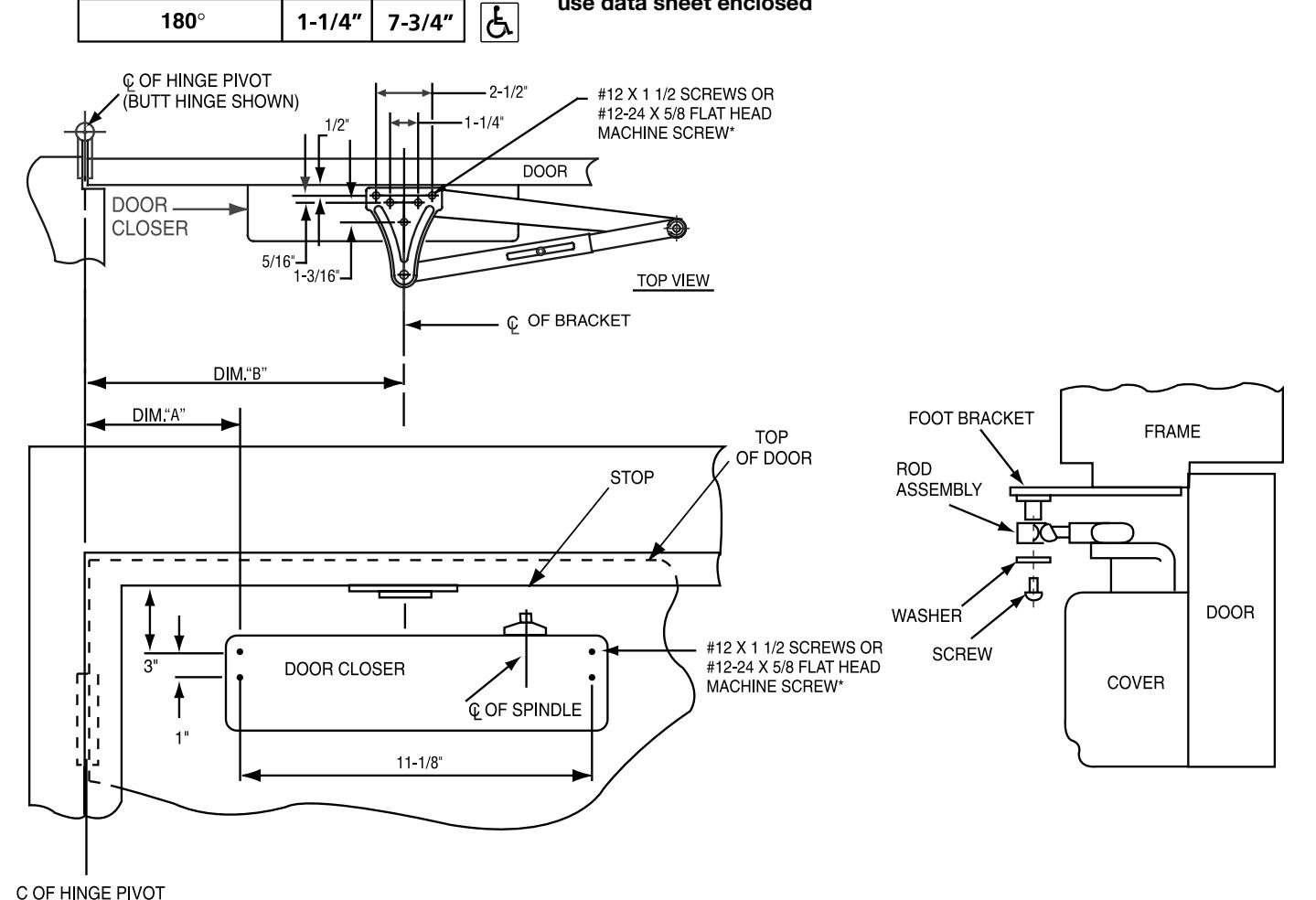
LEFT HAND DOOR SHOWN SAME DIMENSIONS APPLY FOR RIGHT HAND DOOR *SEE PAGE 8 FOR MORTISE NUTS

INSTRUCTIONS FOR INSTALLING PARALLEL ARM APPLICATION
Closer mounted on stop side of door
- 5
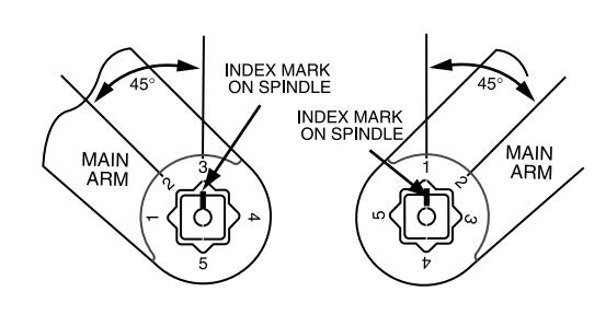
- Install main arm on the closer with index mark on spindle aligned with the number on the arm Note: Left Hand Doors - align index mark with the #4 on the main arm (as shown) Right hand Door - align index mark with the #5 on the main arm (as shown)
- This requires the spindle to be rotated
- Rotate the spindle on the bottom of the closer to align index mark and the required number on the arm
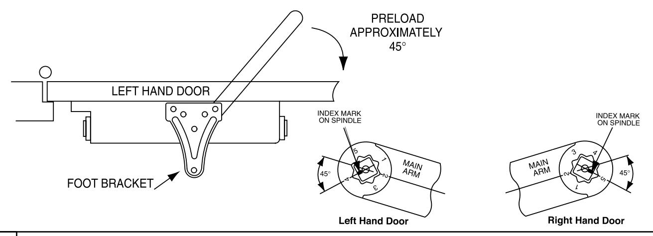
- 6
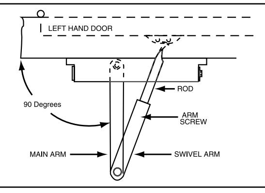
- Opening the door slightly, slide rod into swivel arm and then close the door
- With the door in the closed position, swivel arm so that the pivot is 1-21/2" off the door surface (as shown below)
- Tighten the arm screw securely
Adjust closer as required (See page 8 for details)
ACCESSORY INFORMATION
P4 OR P4A BRACKET P3 OR P3A BRACKET 2-1/2" MIN. SARGENT #590 SHOWN 1430-D DROP BRACKET CLOSER IS MOUNTED ON PLATE WHEN TOP RAIL IS TOO NARROW
FOR FLUSH FRAME AND DOOR CONDITIONS P4A BRACKET IS USED
WITH OVERHEAD HOLDERS
FOR USE WITH OVERHEAD DOOR HOLDERS
TOP JAMB APPLICATION
- Select closer mounting position based Reveal Depth as listed below
- 2
- · Locate and mark hole locations
Note: 3/32" pilot holes are required when Self Tapping Screws are being used If machine screws are being used, use a drill #16 (.177) and a #12-24 tap
- 3
- Install closer body onto the door with 5/8" power adjustment nut end away from hinge
- Install foot & rod assembly onto the frames
|
ARM ASSEMBLY
TYPE |
REVEAL DEPTH | DIM. A |
MAXIMUM
DOOR OPENING |
|---|---|---|---|
| O ARM | 0" TO 2" | 6" | 180° |
| OZ ARM | 2 1/8" TO 5" | 6 3/4" | 140° |
| OZA ARM | 5 1/8" TO 8" | 7 1/2" | 140° |
Note: On the foot & rod assembly, always use the pivot furthest from the hinge
**IF BUTT, FRAME AND WALL CONDITIONS PERMIT, DOOR WILL OPEN
INSTRUCTIONS FOR INSTALLING TOP JAMB
Closer mounted on frame above stop side of door
4
- Install main arm on the closer with index mark on spindle aligned with the number on the arm Note: Left Hand Doors align index mark with the #3 on the main arm (as shown) Right hand Door align index mark with the #1 on the main arm (as shown)
- This requires the spindle to be rotated
- Rotate the spindle on the top of the closer to align index mark and the required number on the arm
5
- Opening the door slightly, slide rod into swivel arm and then close the door
- With the door closed, position the main arm so it is at 90° to the door surface
- Tighten the arm screw securely
6
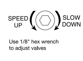
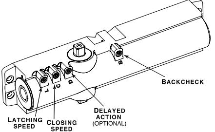
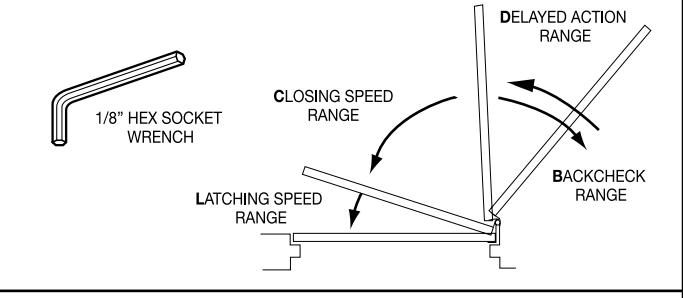
FINAL ADJUSTMENT AND REGULATING PROCEDURE
- Adjust door speed and latching speed valves to achieve the desired closing time. Recommend 6 seconds minimum for 90° to the closed position
- If backcheck is required, adjust valve to achieve a slight cushioning effect. Auxiliary stop required.
- If closer is equipped with delayed action, regulate valve to achieve the desired delay
| NUMBER OF TURNS OF SPRING POWER ADJUSTING NUT | ||
|---|---|---|
|
DOOR WIDTH
(INCHES) |
1431 DOOR CLOSER 👃 | |
| 24-30 | TURN nut 1-3 ( | |
| 30-36 | FACTORY SET | |
| 36-42 | TURN nut 1-4 ) | |
| 42-48 | TURN nut 7-9 ) | |
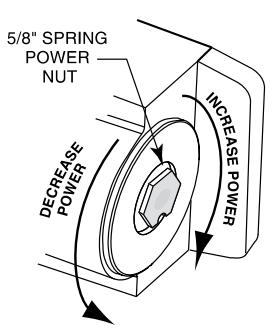
Adjust closing power to the minimum required to reliably close and latch door
- If door is hard to open, decrease power slightly
- If door does not latch, increase power as required
- Use the chart (on the left) as a starting point
- Doors adjusted with high closing power to overcome strong draft conditions may exceed ADA standards
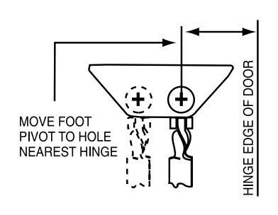
Additional Power Adjustment
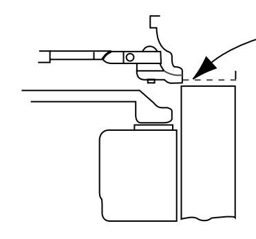
Adjusting foot for additional closing power (for standard and top jamb applications only)
Through Bolts
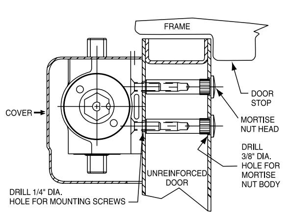
- 1. For top jamb and corner bracket applications: The door closer foot will be attached to the door in a manner similar to that shown for mounting the closer body
- 2. For doors 2-1/4" thick: Mortise nut shown for 1-3/4" thick doors will be furnished along with appropriate length through-bolts, door construction must provide a bridge type reinforcement to prevent the door rail form collapsing with through-bolts are tightened.
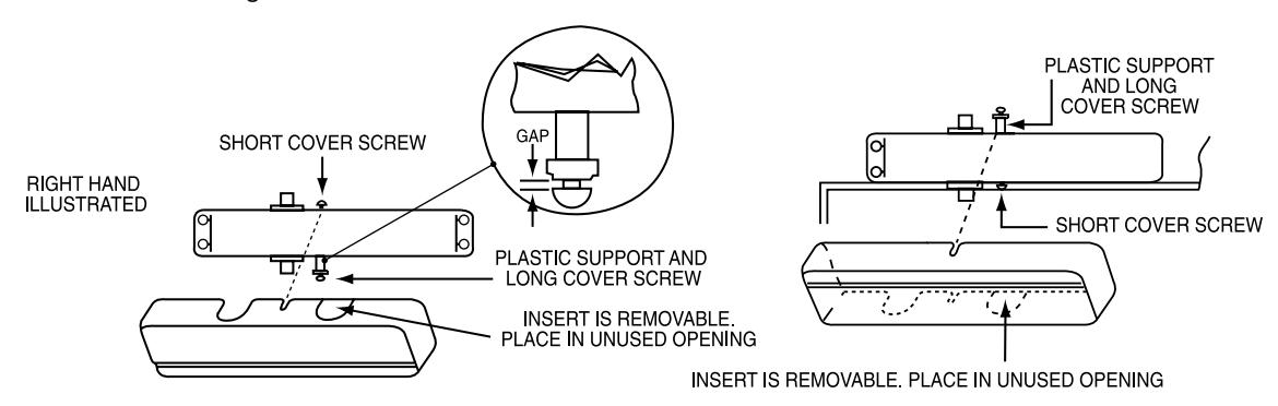
INSTALL COVER AS FOLLOWS:
For standard an parallel arm application
- Screw short cover screw (#8-32 x 5/16") into top of case approximately 2 turns
- Assemble plastic support and long cover screw (#8-32 x 1-1/4") into bottom of case approximately 2 turns
- Hold support against case and slide cover into gap between flange and screw head
- Position cover on closer and tighten screws
For top jamb application
- Assemble plastic support and long cover screw (#8-32 1-1/4") into top of case approximately 2 turns
- Screw short cover screw (#8-32 x 5/16") into bottom of case approximately 2 turns
- Slide cover into gap between flange and screw head. Position cover on closer and tighten screws