1331 Series Door Closer Installation Instructions with JUO (JO & JP9) Arms
Open the original PDF document
View PDFSARGENT® 1331 6 DOOR CLOSER INSTALLATION INSTRUCTIONS WITH JUO (JO & JP9) ARMS

Strength Adjustable From Size 1 Thru 6
CAUTION: FAILURE TO INSTALL OR ADJUST PROPERLY MAY RESULT IN INJURY OR DAMAGE Auxiliary door stop required
FOR ASSISTANCE, CALL SARGENT AT 1-800-727-5477 or www.Sargentlock.com
Choose From 1 of the 3 Applications
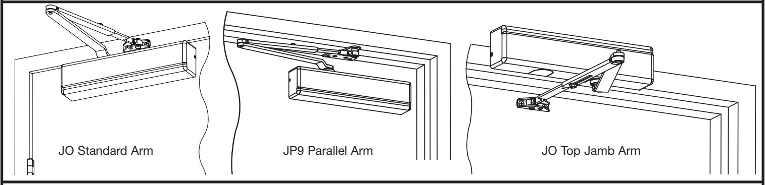
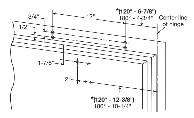
Use Standard & Parallel Full Size Templates Provided
NOTE: With swing clear hinges, use data sheets provided.
*1/4" Variance allowed for retrofit of existing closers
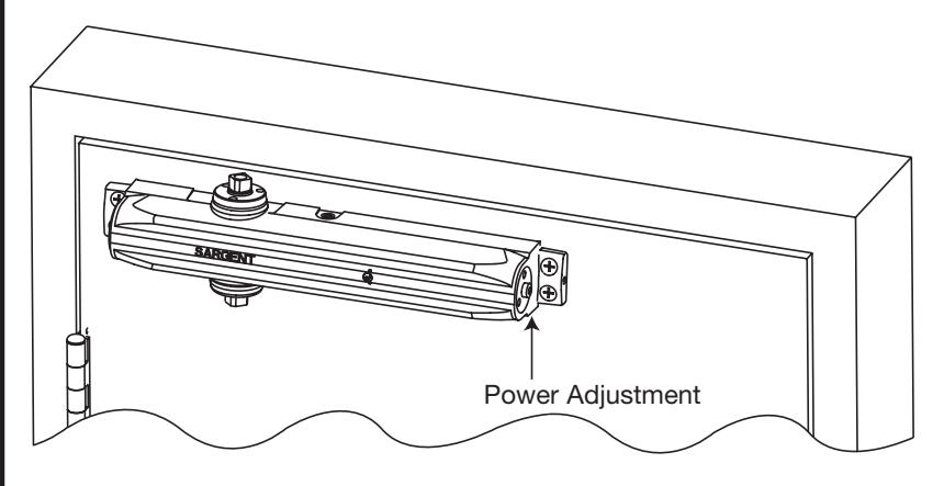
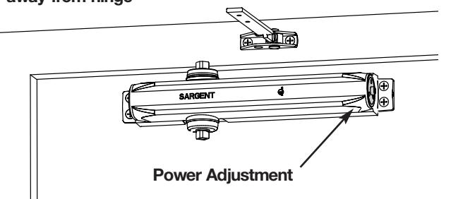
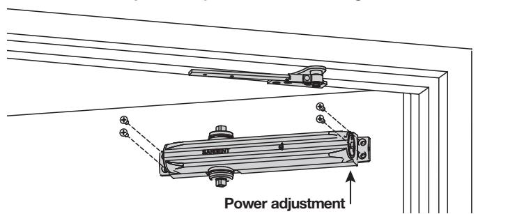
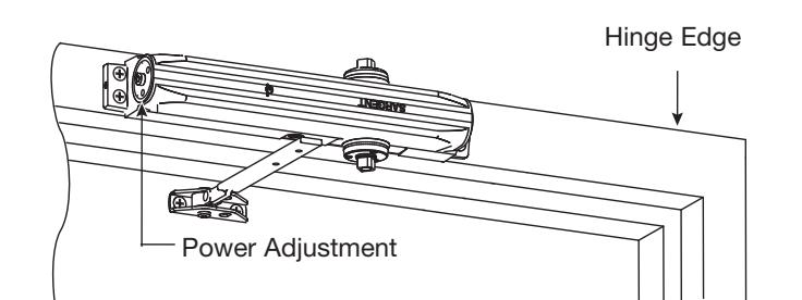
With fasteners provided, secure closer body to door with power adjustment away from hinge.
Copyright © 2008, Sargent Manufacturing Company, an ASSA ABLOY Group company. All rights reserved. Reproduction in whole or in part without the express written permission of Sargent Manufacturing Company is prohibited.
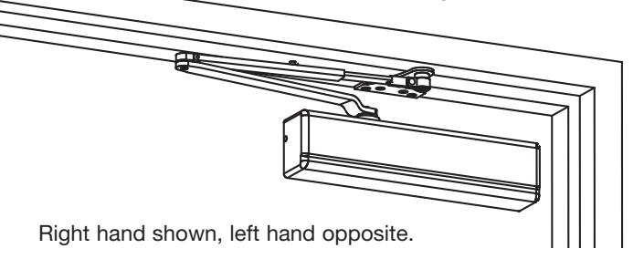
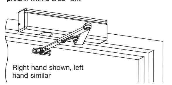
1331 STANDARD APPLICATION JO ARM INSTALLATION INSTRUCTIONS
SARGENT
ASSA ABLOY
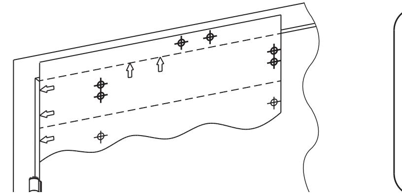
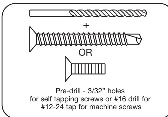
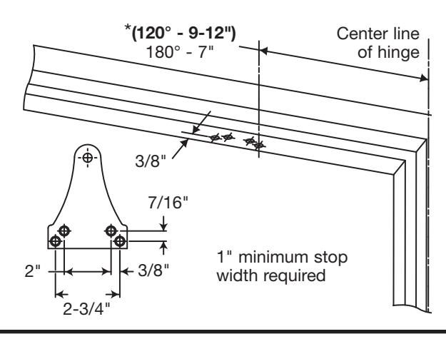
Determine maximum degree of door opening required. Use a #16 drill. Drill and tap door and frame for 12-24 machine screws. When using the included self tapping screw, pre-drill with a 3/32" drill *Provides maximum power for heavy or drafty doors
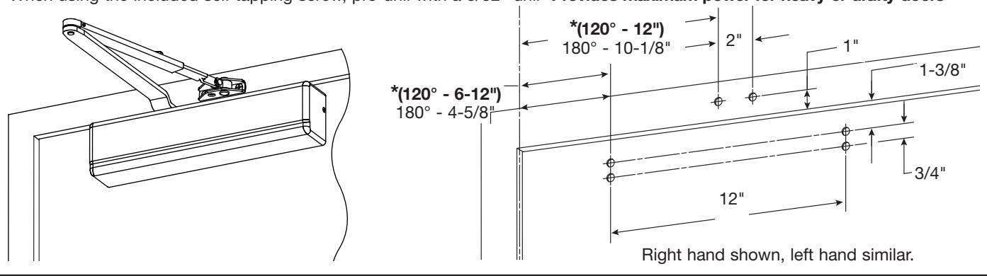
With provided fasteners, install foot to frame and secure closer body to door with power adjustment away from hinge
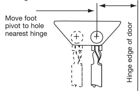
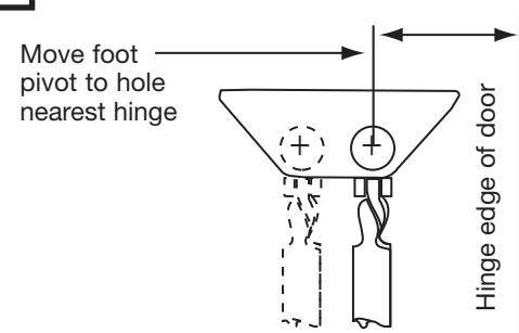
For additional power move foot towards hinge edge of door
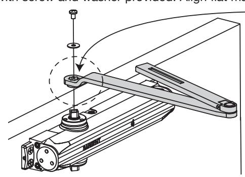
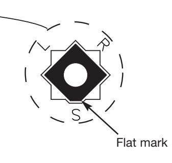
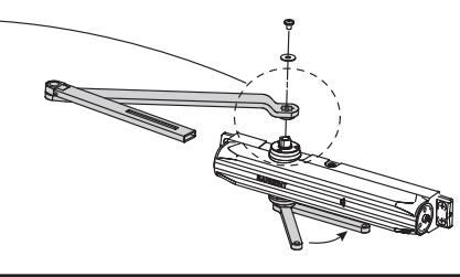
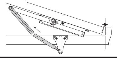
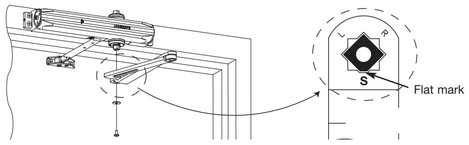
On both right and left hand doors, secure main arm to top spindle with screw and washer provided. Align flat mark as shown
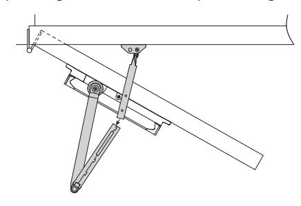
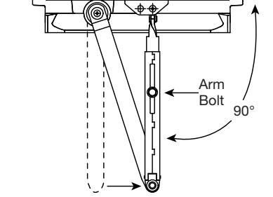
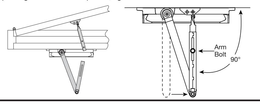
Open door and insert foot into main arm. Close door fully, and while pushing arm as shown in picture, tighten arm bolt
See page 5 for closer adjustment and cover installation
A7741A
ASSA ABLOY, the global leader in door opening solutions
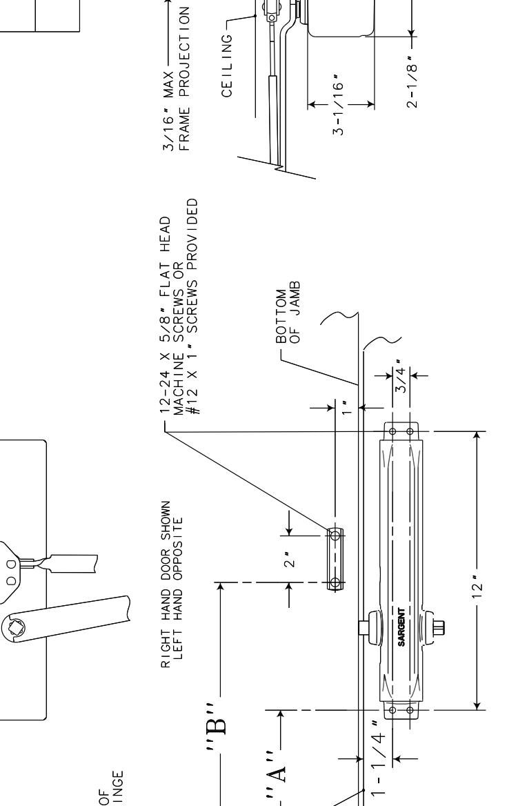
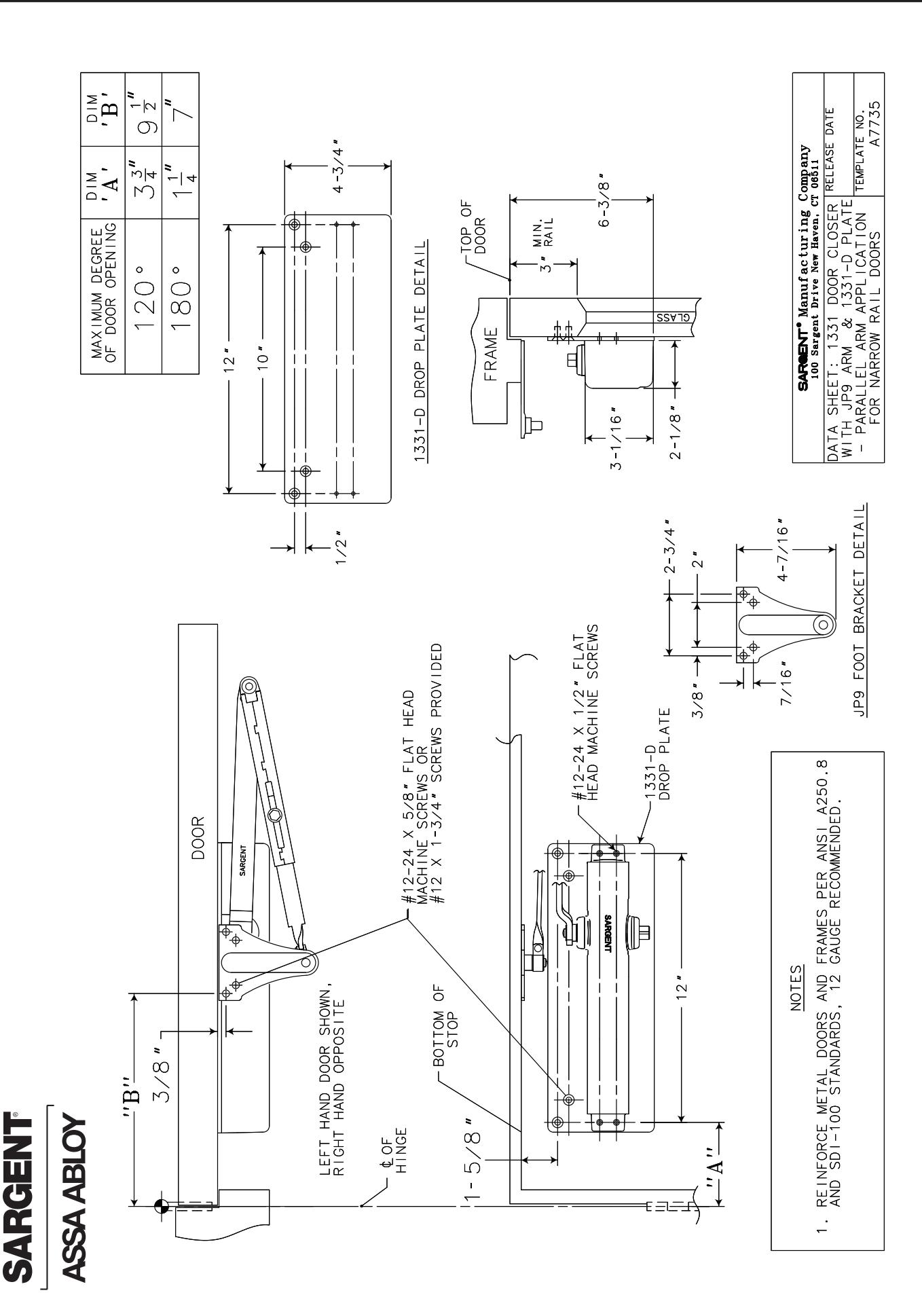
1331 JP9 PARALLEL ARM INSTRUCTIONS
SARGENT
ASSA ABLOY
Determine maximum degree of door opening required. Use a #16 drill. Drill and tap door and frame for 12-24 machine screws. When using the included self tapping screws, predrill with a 3/32"
*Provides maximum power for heavy or drafty doors
Center line of hinge *(120° - 3-3/4") . 180° - 1-1/4"
With fasteners provided, install foot to stop and closer body to door with power adjustment toward hinge
3
With wrench on bottom spindle, preload/index by turning spindle as shown and secure main arm to top spindle with flat mark as indicated at ieft with screw and washer
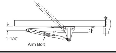
Open door and insert foot into main arm. Close door fully while holding elbow 1-1/4" from door. Tighten arm bolt
5 See page 5 for adjustment and cover installation
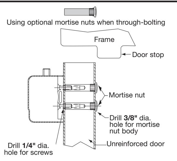
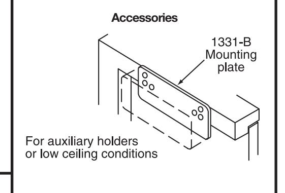
Accessory Information
581-1 Blade Stop Spacer Kit
Metal spacer for use on 1/2" blade stops on aluminum store fronts
ASSA ABLOY, the global leader in door opening solutions
Copyright © 2008, Sargent Manufacturing Company, an ASSA ABLOY Group company. All rights reserved. Reproduction in whole or in part without the express written permission of Sargent Manufacturing Company is prohibited.
1331 JO TOP JAMB INSTRUCTIONS
1 Determine maximum degree of door opening required. Use a #16 drill. Drill and tap door and frame for 12-24 machine screws. When using provided self tapping screws, predrill with a 3/32" drill
Note: 2" maximum reveal allowed
*Provides maximum power for heavy or drafty doors
2 With provided fasteners, install foot to door and closer body to frame with power adjustment away from hinge
2A Adjusting foot for additional closing power
3 On both right and left hand doors, secure main arm to top spindle with screw and washer provided. Align flat mark as shown
4 Open door and insert foot into main arm. Close door fully, and while pushing arm as shown in picture, tighten arm bolt
See page 5 for adjustment and cover installation
4
5
A7741A Copyright © 2008, Sargent Manufacturing Company, an ASSA ABLOY Group company. All rights reserved. Reproduction in whole or in part without the express written permission of Sargent Manufacturing Company is prohibited.
CLOSER ADJUSTMENT AND COVER INSTALLATION
THE 1331 IS FACTORY ADJUSTED FOR MOST APPLICATIONS, HOWEVER, ADDITIONAL ADJUSTMENT MAY BE REQUIRED DUE TO ACTUAL CONDITIONS
5 MINIMUM RECOMMENDED DOOR CLOSING TIME FOR DOORS OPENED TO 90° IS 6 SECONDS.
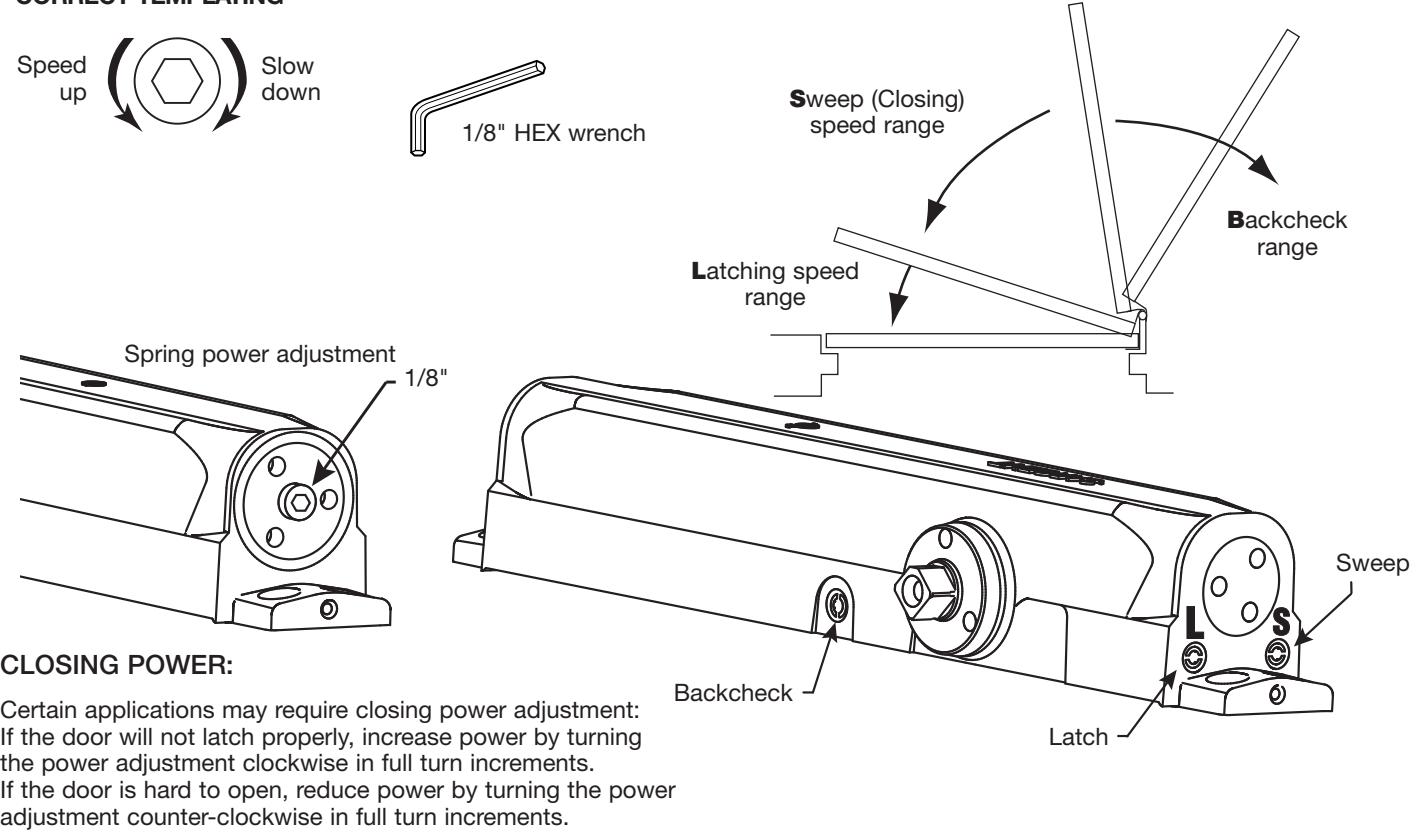
Use 1/8" hex (Allen) wrench to adjust valves as needed
SWEEP AND LATCHING SPEEDS:
Turn valves clockwise to slow down or counterclockwise to speed up door movement
BACKCHECK:
To regulate the intensity of backcheck action, turn valve clockwise to increase or counterclockwise to decrease checking
CAUTION: SET VALVE FOR SLIGHT CUSHIONING EFFECT. CLOSER CAN BE DAMAGED IF THE CHECKING ACTION IS TOO ABRUPT. NEVER USE THE BACKCHECK AS A DOOR STOP. ALWAYS USE A DOOR STOP TO STOP THE DOOR
IF ADJUSTMENTS ARE INEFFECTIVE, CHECK INDEXING AS SHOWN IN STEP 3 AND CHECK FOR CORRECT TEMPLATING
6
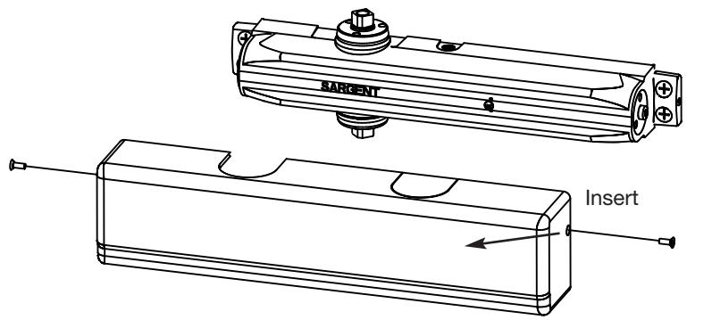
Cover Installation
Move insert if needed. Install cover with two #6- 32 X 5/16" machine screws as shown
A7741A
SARGENT
ASSA ABLOY
| INLULIN 312L |
|---|
| 1547 |
| 1548 |
| 1549 |
DOOR
-¢of HINGE
TOP OF . DOOR
-1540 SERIES 4
FRAME
7 1-3/4" MIN
3-1/2"
CF¥22
2-5/8 " MIN.
<del>д д</del> Вооо
|
Company
T 06511 |
RELEASE DATE |
TEMPLATE NO.
A7746 |
|
|---|---|---|---|
|
SARGENT® Manufacturing Company
100 Sargent Drive New Haven, CT 06511 |
DATA SHEET: |
1540 SERIES OVERHEAD
DARD APPLICATION |
|
1. REINFORCE METAL DOORS & FRAWES PER ANSI A250.8 AND SDI-100 STANDARDS, 12 GAUGE RECOMMENDED. FOR 1540 INSTALLATION, SEE TEMPLATES A7488,A7489 & A7490
2.
NOTES
Copyright © 2008, Sargent Manufacturing Company, an ASSA ABLOY Group company. All rights reserved. Reproduction in whole or in part without the express written permission of Sargent Manufacturing Company is prohibited.
A7741A
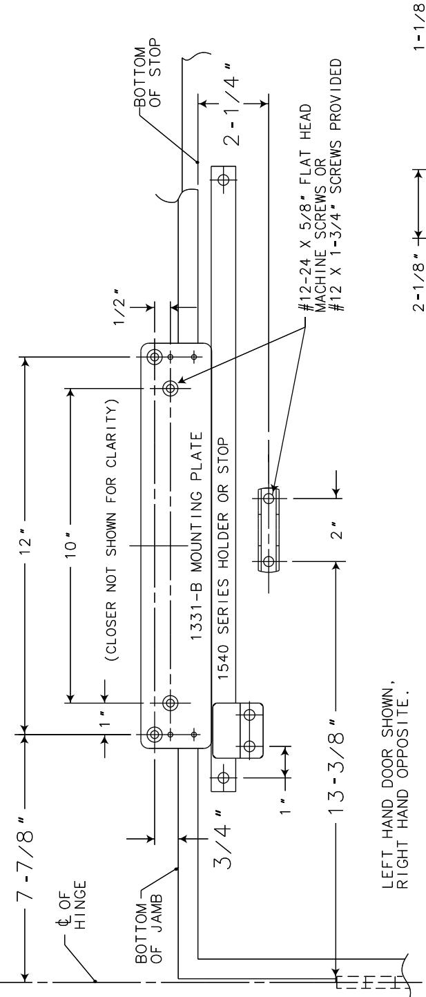
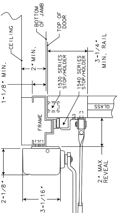
SARGENT® Manufacturing Company 100 Sargent Drive New Haven, CT 06511 DATA SHEET: 1331 DOORS CLOSER RELEASE DATE WITH JOARM & 1540/1530 STOP WITH 1331-B MOUNTING PLATE TOP JAMB APPLICATION A7733 A
3. FOR 1540 STOP/HOLDER INSTALLATION, SEE TEMPLATES A7488 THRU A7490
FOR 1530 HOLDER/STOP INSTALLATION SEE TEMPLATES A7485 THRU A7487
2.
REINFORCE METAL DOORS AND FRAMES PER ANSI A250.8 AND SDI-100 STANDARDS, 12 GAUGE RECOMMENDED.
NOTES
Copyright © 2008, Sargent Manufacturing Company, an ASSA ABLOY Group company. All rights reserved. Reproduction in whole or in part without the express written permission of Sargent Manufacturing Company is prohibited.